related to the discontinuity shape, based on tensile testing of
three flawed specimens of 30CrNiMo8 steel and detecting the
residual magnetic field signals. They proposed a new method
for extracting characteristic parameters, which have a specific
relationship with the loads and can help identify discontinuity
location and shape. Norouzi and Ravanbod (2010) simulated
different lengths of yokes using finite element analysis and
proposed a method to optimize their lengths. Experimental
results showed that optimized yokes improved sensitivity in
detecting discontinuities of different widths without affecting
depth detection, providing an important reference for MFL
detection optimization.
However, none of the above papers considered how the
edge angle of the discontinuity affects the magnetic leakage
signal. In fact, the formation of cracked discontinuities is a
slow process. In addition to the discontinuity as a whole not
necessarily being perpendicular to the direction of magnetiza-
tion during detection, the edge angle of the discontinuity itself
is generally not a right angle (Huang et al. 2023 Meyer et al.
2016). Therefore, Dharmawan et al. (2022) classified engineer-
ing discontinuities as semi-elliptical, rectangular, combined
(trapezoidal), triangular, and hole-shaped by algorithmically
segmenting the discontinuities and changing the detector
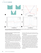
orientation. In this research, we found that for the specific
V-shaped and trapezoidal discontinuities with the same
magnetization and MFL sensor positioning, the MFL signal
changes with the discontinuity edge angle. To explore the rela-
tionship between the two and the rule of change, we decided
to study how the same type of discontinuities with different
edge angles affect the magnetic leakage signal.
This paper, based on Maxwell’s system of equations and ray
optics theory (Bulgakov and Fedorin 2012 Yi et al. 2016), and
considering the magnetic refraction phenomenon of magnetic
field lines in different mediums (Assylbekov and Yang 2015),
investigates the influence of the discontinuity’s edge angle on
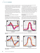
the magnetic leakage signal. By studying V-shaped and trape-
zoidal discontinuities, we subjected the different edge angles
of each discontinuity shape to finite element simulations and
experimental verification, establishing regression equations
between the edge angles and magnetic leakage signals to
analyze the characteristic relationship between the two.
In the field of NDT, many scholars have studied discontinu-
ity leakage magnetic detection from different dimensions and
directions. In this paper, we focus on the discontinuity’s edge
angle, conducting a two-dimensional study to establish the
relationship between the edge angle and the magnetic leakage
signal. This research introduces a new consideration for dis-
continuity reconstruction that improves the accuracy of recon-
struction, and injects new ideas and methods for further study
in this field.
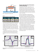
Leakage Detection Principle and Model
MFL is based on the magnetic flux leakage effect triggered by
the change of material magnetoresistance, and the discontinu-
ity identification is realized by capturing the magnetic leakage
signal through the sensor. This paper combines the system of
Maxwell’s equations with the theory of magnetic field refrac-
tion to study and analyze the trend of the influence of the edge
angle of the discontinuity on the leakage magnetic field char-
acteristics through finite element simulation.
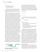
Leakage Detection Principle
MFL is a method commonly used to detect discontinuities on
or near the surface of metals. Based on the magnetic induc-
tion effect and the magnetic properties of the material, the
magnetic field generates magnetic flux on the surface and near
the surface of the sample, which is related to the magnetic
properties and shape of the sample. If a discontinuity exists
on or near the surface of the sample, the magnetoresistance
at the discontinuity increases, causing a leakage of magnetic
flux near the discontinuity. This change can be captured by
sensors on the inspection probe to determine whether there
is a discontinuity on or near the surface of the sample and to
determine the shape of the discontinuity. If no discontinuities
exist, the magnetic susceptibility is uniformly distributed inside
the sample, and the magnetic susceptibility outside the sample
is almost negligible. Therefore, it is possible to objectively
evaluate a discontinuity by measuring the magnetic induction
strength at the discontinuity using a sensor.
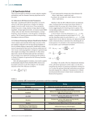
Theoretical Analysis
Since this is a static magnetic field problem, the relationship
can be expressed theoretically through a system of partial dif-
ferential equations that describe the relationship between the
electric and magnetic fields, as well as the charge and current
densities, i.e., Maxwell’s system of equations:
(1) ∇ ×H − ∂ D
∂ t
=J
(2) ∇ ×E − ∂ B
∂ t
=0
(3) ∇ ×B =0
(4) ∇ ×D =ρ
where
D is the potential displacement vector in C/m2,
H is the magnetic field strength in A/m,
J is the current density in A/m2,
B is the magnetic induction in Wb/m2,
E is the electric field strength in V/m,
ρ is the charge density in C/m2, and
∇ is the Hamiltonian operator (Szalay 2017 Zharinov 2017).
Furthermore, in addition to the above equations, the intrin-
sic relational equations for the medium of interest are also
required:
(5) D =εE B =μH J =σE
M AY 2 0 2 5 • M AT E R I A L S E V A L U AT I O N 31
three flawed specimens of 30CrNiMo8 steel and detecting the
residual magnetic field signals. They proposed a new method
for extracting characteristic parameters, which have a specific
relationship with the loads and can help identify discontinuity
location and shape. Norouzi and Ravanbod (2010) simulated
different lengths of yokes using finite element analysis and
proposed a method to optimize their lengths. Experimental
results showed that optimized yokes improved sensitivity in
detecting discontinuities of different widths without affecting
depth detection, providing an important reference for MFL
detection optimization.
However, none of the above papers considered how the
edge angle of the discontinuity affects the magnetic leakage
signal. In fact, the formation of cracked discontinuities is a
slow process. In addition to the discontinuity as a whole not
necessarily being perpendicular to the direction of magnetiza-
tion during detection, the edge angle of the discontinuity itself
is generally not a right angle (Huang et al. 2023 Meyer et al.
2016). Therefore, Dharmawan et al. (2022) classified engineer-
ing discontinuities as semi-elliptical, rectangular, combined
(trapezoidal), triangular, and hole-shaped by algorithmically
segmenting the discontinuities and changing the detector
orientation. In this research, we found that for the specific
V-shaped and trapezoidal discontinuities with the same
magnetization and MFL sensor positioning, the MFL signal
changes with the discontinuity edge angle. To explore the rela-
tionship between the two and the rule of change, we decided
to study how the same type of discontinuities with different
edge angles affect the magnetic leakage signal.
This paper, based on Maxwell’s system of equations and ray
optics theory (Bulgakov and Fedorin 2012 Yi et al. 2016), and
considering the magnetic refraction phenomenon of magnetic
field lines in different mediums (Assylbekov and Yang 2015),
investigates the influence of the discontinuity’s edge angle on
the magnetic leakage signal. By studying V-shaped and trape-
zoidal discontinuities, we subjected the different edge angles
of each discontinuity shape to finite element simulations and
experimental verification, establishing regression equations
between the edge angles and magnetic leakage signals to
analyze the characteristic relationship between the two.
In the field of NDT, many scholars have studied discontinu-
ity leakage magnetic detection from different dimensions and
directions. In this paper, we focus on the discontinuity’s edge
angle, conducting a two-dimensional study to establish the
relationship between the edge angle and the magnetic leakage
signal. This research introduces a new consideration for dis-
continuity reconstruction that improves the accuracy of recon-
struction, and injects new ideas and methods for further study
in this field.
Leakage Detection Principle and Model
MFL is based on the magnetic flux leakage effect triggered by
the change of material magnetoresistance, and the discontinu-
ity identification is realized by capturing the magnetic leakage
signal through the sensor. This paper combines the system of
Maxwell’s equations with the theory of magnetic field refrac-
tion to study and analyze the trend of the influence of the edge
angle of the discontinuity on the leakage magnetic field char-
acteristics through finite element simulation.
Leakage Detection Principle
MFL is a method commonly used to detect discontinuities on
or near the surface of metals. Based on the magnetic induc-
tion effect and the magnetic properties of the material, the
magnetic field generates magnetic flux on the surface and near
the surface of the sample, which is related to the magnetic
properties and shape of the sample. If a discontinuity exists
on or near the surface of the sample, the magnetoresistance
at the discontinuity increases, causing a leakage of magnetic
flux near the discontinuity. This change can be captured by
sensors on the inspection probe to determine whether there
is a discontinuity on or near the surface of the sample and to
determine the shape of the discontinuity. If no discontinuities
exist, the magnetic susceptibility is uniformly distributed inside
the sample, and the magnetic susceptibility outside the sample
is almost negligible. Therefore, it is possible to objectively
evaluate a discontinuity by measuring the magnetic induction
strength at the discontinuity using a sensor.
Theoretical Analysis
Since this is a static magnetic field problem, the relationship
can be expressed theoretically through a system of partial dif-
ferential equations that describe the relationship between the
electric and magnetic fields, as well as the charge and current
densities, i.e., Maxwell’s system of equations:
(1) ∇ ×H − ∂ D
∂ t
=J
(2) ∇ ×E − ∂ B
∂ t
=0
(3) ∇ ×B =0
(4) ∇ ×D =ρ
where
D is the potential displacement vector in C/m2,
H is the magnetic field strength in A/m,
J is the current density in A/m2,
B is the magnetic induction in Wb/m2,
E is the electric field strength in V/m,
ρ is the charge density in C/m2, and
∇ is the Hamiltonian operator (Szalay 2017 Zharinov 2017).
Furthermore, in addition to the above equations, the intrin-
sic relational equations for the medium of interest are also
required:
(5) D =εE B =μH J =σE
M AY 2 0 2 5 • M AT E R I A L S E V A L U AT I O N 31