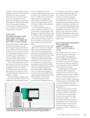
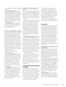
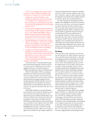
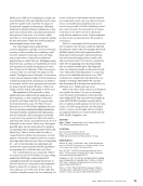
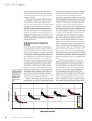
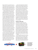
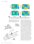
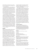
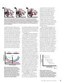
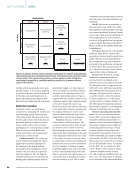
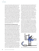
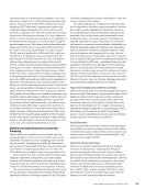
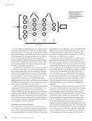
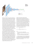
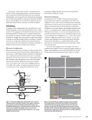
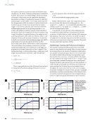
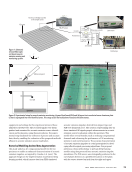
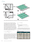
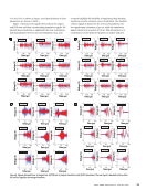
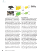
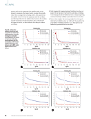
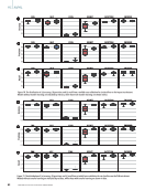
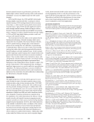
NDT application being addressed. This includes the use of test data to ensure the intent of the application is being met and that the available data meets the needs of the application before a com- prehensive validation study is accomplished. The output of the ADA diagnostic is not the final dis- position of an indication. Depending on the appli- cation, the output enables inspectors to focus their attention on portions of the inspection data that have features of possible indications by screen- ing data with no attributes of a possible flaw. Alternatively, the output can be used to provide guidance on the nature of an indication so the proper disposition process can be rapidly iden- tified and implemented, minimizing the time a system is in the inspection stage of a maintenance process. The key attribute of this approach is the human inspector remains in the loop. The inspec- tor functions to ensure data quality, data fidelity, and can review any ADA outputs to make the final determination regarding an indication. Representative DAF Successes The following represents several examples devel- oped by AFRL and transitioned to the DAF. The ADA capabilities are presented as a function of increasing complexity from the perspective of combining the three technical approaches outlined in the previous section. However, this order should not be considered a listing of increasing complex- ity as each application had its unique degrees of complexity and used different approaches to tailor to the need and to the desired outcome of the inspection. A representative application that emphasizes the use of heuristics occurs in the manufactur- ing of aerospace composite structures, especially primary load carrying structures such as wing and fuselage skins. These parts require 100% ultrasonic inspection to detect delaminations and porosity where common rejection criteria are for delamina- tions greater than 6.35 mm (0.25 in.) in diameter or porosity that exceeds 2%. When considering the large areas to be inspected at manufacturing (note: this is not a requirement once a system is fielded), a bottleneck in the production flow can occur with the large volume of data to be assessed by inspec- tors. To minimize this bottleneck, a heuristic-based algorithm was developed to closely mimic the steps taken by an inspector to review data collected from these inspections (Aldrin et al. 2016). The ADA algorithm leverages the available A-scan and B-scan data that accompanies the C-scan data. Multiple steps are taken in each of the three data representations to determine if an indication has features associated with delami- nations that exceed the reject criteria. The repre- sentative result is shown in Figure 4 where C-scan features are identified as suspected defects and others are identified as benign. Though both may appear similar in the C-scan, attributes of the front wall, back wall, and volumetric gating can be used to distinguish between acceptable and rejectable features. The rejectable features are highlighted to the trained inspector who makes the final determi- nation regarding the indication. With this approach, inspection processes have been greatly acceler- ated, though exact metrics are not available for publication. Another representative case study includes the use of both simulation and heuristics to identify defects and discriminate between types of defects. The specific application is for rotating turbine engine components evaluated by an automated inspection system that can provide highly regis- tered data. Using a combination of model-based assessments and heuristic analysis methods, the response from data with varying probe conditions can be evaluated and provide guidance on what features are from suspected indications and what are due to the probe variability (Aldrin et al. 2019b). A representative illustration of this approach is the experimental response from a subsurface nonme- tallic inclusion in the presence of probe variation Gap Thickness transition Pad up Scan edge Part edge Lap Wrinkle Embedded defects Figure 4. Ultrasonic C-scan of a composite test article indicating regions identified by the assisted data analysis algorithms as potential defects. J U L Y 2 0 2 3 • M A T E R I A L S E V A L U A T I O N 39 2307 ME July dup.indd 39 6/19/23 3:41 PM

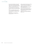
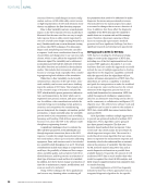
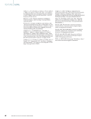
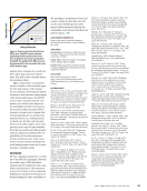
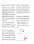
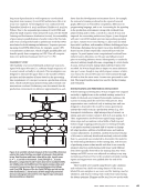
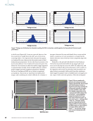
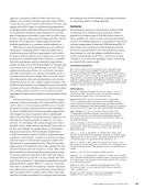
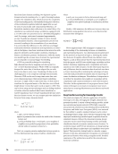
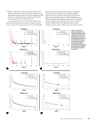
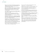
and material noise. Final results from iterative comparison and adjustments of the model data, being compared in impedance planes, are shown in Figure 5 and highlight the ability to evaluate the buried nonmetallic inclusion size and depth. Additional steps in the development process resulted in the ADA algorithms providing guidance to the inspectors when features in the data indicate when a fatigue crack is emanating from a nonme- tallic inclusion. The ADA being developed for this application is in its final stages of refinement before it will be evaluated by a formal validation process. The third example combines elements of heu- ristics, simulations, and large dataset analysis to realize a successful outcome on a very complex inspection. The application addresses the lower forward spar cap on C-130 aircraft (Lindgren et al. 2005), as shown in Figure 6. The approach leverages development at the academic level for both the generation and detection of ultrasonic creeping waves (Nagy et al. 1994), plus the use of algorithms to discern the presence of cracks in a less complex, but still challenging, application (Aldrin et al. 2001). As described in Lindgren et al. (2005), the solution included the use of ana- lytical methods to fully represent the propagation paths within the structure simulation tools to explore various attributes of the inspection data as it propagates in the structure plus, the use of advanced processing methods, namely echo dynamics and local correlation functions, to dis- criminate between responses from potential flaws to those from other geometric reflectors found intermittently in the structure. In addition, over 2000 representative inspection opportunities Scan, x (mils) –50 0 50 20 10 0 –10 –200 –50 0 50 Scan, x (mils)ls)i –50 0 50 20 10 0 –100 20 10 0 –100 –200 –50 0 50 Scan, x (mils) –50 0 50 –50 0 50 Scan, x (mils) –50 0 50 10 5 0 –5– –10 –50 0 50 S (mils) – 0 – (m ––20 ––30 0 S – 0 Figure 5. Model fit (a) to experimental data (b) for the vertical (top) and horizontal (bottom) representations of eddy current scans from a sub-surface nonmetallic particle with differences due to probe and material variability. FEATURE |AI/ML Typical crack Typical crack Web Lower panel Beam cap Front beam cap WS 174 Up Aft Outboard Trace of web splice tee WS 178 Bulkhead WS 80.5 Figure 6. Lower forward spar cap of the C-130 illustrating the complexity of the regions to be inspected. 40 M A T E R I A L S E V A L U A T I O N • J U L Y 2 0 2 3 2307 ME July dup.indd 40 6/19/23 3:41 PM Index, y Index, y Index, y Index, y I (m(mils) I (m(mils) (m(mils) (m(mils)
ASNT grants non-exclusive, non-transferable license of this material to  .
All rights reserved. © ASNT 2026. To report unauthorized use, contact: customersupport@asnt.org