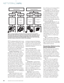
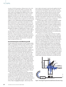
There have been several attempts to support the reali- zation of ZDM in RSW through the use of adaptive welding systems. Conceptually, modern adaptive welding systems monitor one or more indirect proxies of weld progress (e.g., dynamic resistance curves, current, voltage, force, tip dis- placement [El-Banna 2006 Neugebauer et al. 2013 Reis et al. 2016]), process these monitored features in real time to create feedback, and serve the feedback to an algorithm that adapts weld process parameters (e.g., weld time, force, and current) accordingly. In practice, these proxies do not produce suffi- ciently reliable and consistent feedback for adaptive weld con- trollers, so these systems generally fail to meet expectations and consequently many users revert to fixed schedules with adaptive capabilities disabled. RSW is well-positioned to simultaneously meet the require- ments of NDE 4.0 and achieve a breakthrough in ZDM, largely due to recent advancements in RSW NDE research. RSW NDE can be conducted either in-process (during the weld) or post-process (after the weld) using a variety of NDE modalities (Runnemalm and Appelgren 2012 Summerville et al. 2019). One of the most prevalent modalities is ultrasound (Chertov and Maev 2004 Denisov et al. 2004 Ouellette et al. 2013 Maev et al. 2014, 2016 Sung Hoon et al. 2020). Ultrasonic inspection has important advantages in inspection speed, insensitivity to sample thickness, adaptability, and the ability to directly inspect the internal geometric properties of the joint. The current state of the art in ultrasonic NDE for RSW consists of post-process offline inspection via portable ultrasonic systems with 2D matrix probes (e.g., Denisov et al. 2004 Maev et al. 2005), post-process robotized in-line systems with a similar ultrasonic configuration, and in-line real-time process moni- toring systems using single-element probes (e.g., Chertov and Maev 2004 Ouellette et al. 2013 Maev et al. 2013, 2014 Sung Hoon et al. 2020). In any case, many NDE 4.0 requirements are already being met for such inspection systems, but only the in-line approach can provide real-time process monitoring and NDE data with 100% joint coverage, which is actionable in the context of an adaptive welding system that facilitates ZDM. In its current form, the in-line inspection approach involves embedding a single-element ultrasonic transducer into a welding electrode (Chertov and Maev 2004 Ouellette et al. 2013 Maev et al. 2014, 2016 Sung Hoon et al. 2020). The transducer is immersed in flowing water, which both cools the transducer and provides coupling. The copper electrode caps focus the ultrasonic waves into the heat-affected zone of the workpiece and provide coupling against the stackup due to the application of intense force during welding (Maev and Chertov 2010). Throughout the welding process, A-scans are sampled every millisecond in pulse-echo mode, aiming through the center of the weld region between the electrodes. An M-scan—a 2D ultrasonic signature of the weld process—is then formed by horizontally stacking A-scans, and currently only post-process interpretation of the ultrasonic signature is con- ducted for quality control (Maev et al. 2021). Therefore, toward adaptive welding, a major missing piece in existing in-line ultrasonic systems is real-time interpretation of the sequence of A-scan signals as they are collected. Classically, ultrasonic NDE data interpretation may involve signal/image processing, statistical analyses, search algorithms, model fitting, and hand-coded rules for decision-making. In some cases, these classical approaches are sufficient. However, in many application domains, such as RSW inspection—due to the many potential geometries, material combinations, and weld parameterizations, which can be encountered in a production environment—these approaches fail to meet the required performance, inference speed, and generality. Recently, deep learning approaches have been increasingly applied, to great effect, to a variety of problems in ultrasonic NDE data interpretation spanning essentially all use cases and specific tasks (e.g., defect detection and characterization, measurement automation, and so on [Cantero-Chinchilla et al. 2022 Taheri et al. 2022]). For example, Virkkunen et al. (2021) used a convolutional neural network (CNN) for crack detec- tion in ultrasonic inspection data from butt-fused stainless steel pipes. Similarly, Shafiei Alavijeh et al. (2020) developed an ultrasonic inspection approach using a chord transducer for butt-fused plastic pipe joints. In this case, they used an autoen- coder to conduct outlier detection on A-scans. Subsequently, the group developed an approach that classified A-scans in terms of defect presence/absence and according to defect type when a defect is detected (Shafiei Alavijeh et al. 2021). They compared several classical machine learning algorithms to four deep neural network architectures and determined that a CNN generally achieved the best performance on this task. Guo et al. (2019) combined CNN with recurrent neural networks (gated recurrent unit [GRU] and long short-term memory [LSTM]) to achieve high-performance debonding defect detection in ultrasonic C-scans of braided composite materials. They subsequently refined the approach in later works by instead framing the problem as semantic segmen- tation (Guo et al. 2023). Huang et al. (2022) also combined CNN and LSTM to detect defects in copper pipes in data from laser ultrasonic scanning. Maev et al. (2021) used an object detection approach with YOLOv3 (the “you-only-look-once” v3 object detector) to conduct post-process characterization of ultrasonic weld process signatures by identifying expulsions (discharge of molten material from the stackup due to intense pressure and rapid heating), while also identifying discrete weld-process events and measuring the position of the nugget at its maximum vertical size within the welded stackup. A more recent study by Zamiela et al. (2023) combined infrared with ultrasonic imaging data and developed a two-branch U-Net, which conducts semantic segmentation on the aligned images simultaneously to identify and characterize pores in metal structures in a single, unified output map. Deep learning has been proven to outperform classical computational NDE data interpretation approaches in terms of performance, inference speed, and generality thus, it is a promising potential solution for time-sensitive contexts such as real-time inspection and adaptive welding. ME |AI/ML 62 M A T E R I A L S E V A L U A T I O N • J U L Y 2 0 2 3 2307 ME July dup.indd 62 6/19/23 3:41 PM

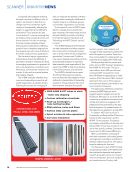
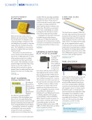
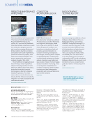
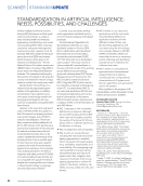
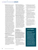
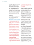
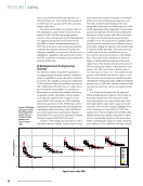
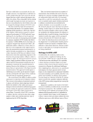
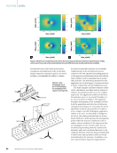
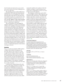
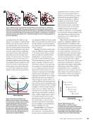
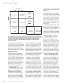
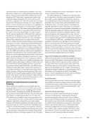
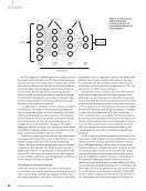
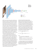
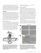
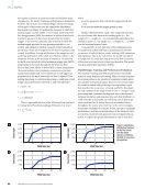
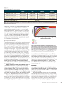
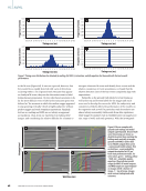
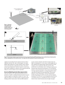
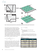
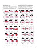
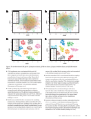
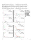
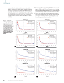
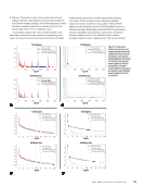
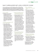
The purpose of this study was first to investigate the fea- sibility of a deep learning approach for real-time interpreta- tion of ultrasonic NDE data from RSW process monitoring. Subsequently, a novel approach was developed and evaluated for real-time characterization of ultrasonic data from the RSW process, which adheres to the needs of an adaptive weld con- troller that requires either continuous or discrete feedback. Methodology A summary of the experimental work is provided here, and a detailed description of the methodology follows. First, a large dataset of weld samples was developed with ultrasonic process monitoring enabled. Subsequently, a machine learning task was devised, the outputs of which could be used as actionable feedback for welding. The ultrasonic M-scan data were labeled to produce a machine learning dataset accordingly. A feasibil- ity study was conducted to identify neural network architec- tures to perform the task within time constraints, and finally a feasible neural network was trained and evaluated. Ultrasonic Configuration Ultrasonic data were collected using an in-line real-time ultra- sonic process monitoring system for spot welding (Figure 1). In this system, a 12 MHz single-element transducer is embedded into a welding electrode and immersed in water to keep the transducer cool the water also acts as an ultrasound couplant. The transducer aims through the center of the weld region, between the electrodes. Ultrasonic A-scans are obtained every 1 ms in pulse-echo mode with a sampling frequency of 125 MHz. The number of samples in a given A-scan was set such that the entire stackup was visible in the A-scan throughout welding. Resultant M-scans were composed by horizontally stacking the A-scans. Dataset Development A weld dataset of 18 223 RSWs, with the ultrasonic process monitoring system enabled, was developed. The welds were designed to cover a wide variety of weld geometries, materials, and parameters that are observed in automotive assembly. The dataset covered more than 80 sheet thickness combinations including 2- and 3-sheet similar- and dissimilar-material welds of 0.65–2.0 mm sheets made of mild and high-strength steels. Weld times varied from 75 to 400 ms, force ranged from 300 to 1000 kN, and current from 6 to 13 kA. Resultant welds were fab- ricated with diameters ranging from 0 to ~10 mm, with vertical maximum nugget size proportional to stack of ~0.0–0.8, and in some cases expulsions were purposely induced. Resultant M-scans were generally 75–400 pixels wide (based on weld time) and 100–400 pixels high (based on A-scan length, which varies by stack size). For each weld, alongside its M-scan (Figure 2a), various metadata were captured, such as current-on timing, current-off timing, sheet thicknesses, and so forth. Metadata were used in the data preprocessing and augmentation stages to compute Figure 1. Ultrasonic configuration schematic for in-line real-time ultrasonic process monitoring system for spot welding. Ultrasonic waves (gray) are transmitted into the welded stack every 1 ms throughout welding process, and the transducer receives reflected waves as A-scan signals. The graphic shows an instant of an asymmetrical two-sheet weld already in progress (i.e., the molten nugget has been formed). Transducer cable Ultrasonic transducer Electrode cap Electrode cap Top sheet Bottom sheet Ultrasonic wave Electrode shank Molten nugget Melting SSID Nugget top Saturation Expulsion Nugget bottom Stack top Stack bottom Non-weld Weld time (ms) Nominal 0 2650 0 2650 0 400 Insufficient Expulsion 0 400 Figure 2. Ultrasonic M-scan samples from welds of same stackup but varying quality: (a) ultrasonic time of flight (Y axis) given the weld time (X axis). The top-left weld fails to breach the steel-steel interface, top-right weld insufficiently penetrates top sheet, bottom- left weld is ideal, and bottom-right weld features an expulsion (abrupt discontinuity in weld process). (b) Ultrasonic M-scan sample labeled for deep learning model development. J U L Y 2 0 2 3 • M A T E R I A L S E V A L U A T I O N 63 2307 ME July dup.indd 63 6/19/23 3:41 PM T of flight (ns)
ASNT grants non-exclusive, non-transferable license of this material to  .
All rights reserved. © ASNT 2026. To report unauthorized use, contact: customersupport@asnt.org