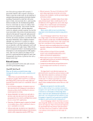
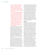
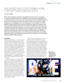
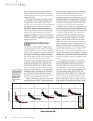
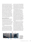
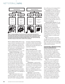
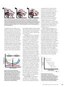
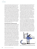
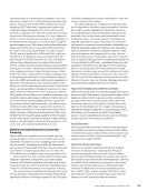
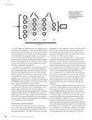
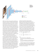
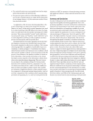
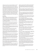
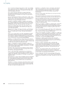
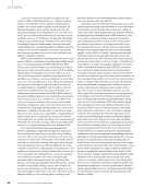
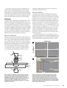
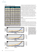
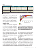
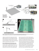
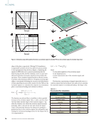
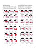
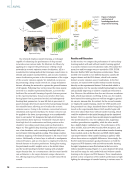
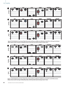
The purpose of this study was first to investigate the fea- sibility of a deep learning approach for real-time interpreta- tion of ultrasonic NDE data from RSW process monitoring. Subsequently, a novel approach was developed and evaluated for real-time characterization of ultrasonic data from the RSW process, which adheres to the needs of an adaptive weld con- troller that requires either continuous or discrete feedback. Methodology A summary of the experimental work is provided here, and a detailed description of the methodology follows. First, a large dataset of weld samples was developed with ultrasonic process monitoring enabled. Subsequently, a machine learning task was devised, the outputs of which could be used as actionable feedback for welding. The ultrasonic M-scan data were labeled to produce a machine learning dataset accordingly. A feasibil- ity study was conducted to identify neural network architec- tures to perform the task within time constraints, and finally a feasible neural network was trained and evaluated. Ultrasonic Configuration Ultrasonic data were collected using an in-line real-time ultra- sonic process monitoring system for spot welding (Figure 1). In this system, a 12 MHz single-element transducer is embedded into a welding electrode and immersed in water to keep the transducer cool the water also acts as an ultrasound couplant. The transducer aims through the center of the weld region, between the electrodes. Ultrasonic A-scans are obtained every 1 ms in pulse-echo mode with a sampling frequency of 125 MHz. The number of samples in a given A-scan was set such that the entire stackup was visible in the A-scan throughout welding. Resultant M-scans were composed by horizontally stacking the A-scans. Dataset Development A weld dataset of 18 223 RSWs, with the ultrasonic process monitoring system enabled, was developed. The welds were designed to cover a wide variety of weld geometries, materials, and parameters that are observed in automotive assembly. The dataset covered more than 80 sheet thickness combinations including 2- and 3-sheet similar- and dissimilar-material welds of 0.65–2.0 mm sheets made of mild and high-strength steels. Weld times varied from 75 to 400 ms, force ranged from 300 to 1000 kN, and current from 6 to 13 kA. Resultant welds were fab- ricated with diameters ranging from 0 to ~10 mm, with vertical maximum nugget size proportional to stack of ~0.0–0.8, and in some cases expulsions were purposely induced. Resultant M-scans were generally 75–400 pixels wide (based on weld time) and 100–400 pixels high (based on A-scan length, which varies by stack size). For each weld, alongside its M-scan (Figure 2a), various metadata were captured, such as current-on timing, current-off timing, sheet thicknesses, and so forth. Metadata were used in the data preprocessing and augmentation stages to compute Figure 1. Ultrasonic configuration schematic for in-line real-time ultrasonic process monitoring system for spot welding. Ultrasonic waves (gray) are transmitted into the welded stack every 1 ms throughout welding process, and the transducer receives reflected waves as A-scan signals. The graphic shows an instant of an asymmetrical two-sheet weld already in progress (i.e., the molten nugget has been formed). Transducer cable Ultrasonic transducer Electrode cap Electrode cap Top sheet Bottom sheet Ultrasonic wave Electrode shank Molten nugget Melting SSID Nugget top Saturation Expulsion Nugget bottom Stack top Stack bottom Non-weld Weld time (ms) Nominal 0 2650 0 2650 0 400 Insufficient Expulsion 0 400 Figure 2. Ultrasonic M-scan samples from welds of same stackup but varying quality: (a) ultrasonic time of flight (Y axis) given the weld time (X axis). The top-left weld fails to breach the steel-steel interface, top-right weld insufficiently penetrates top sheet, bottom- left weld is ideal, and bottom-right weld features an expulsion (abrupt discontinuity in weld process). (b) Ultrasonic M-scan sample labeled for deep learning model development. J U L Y 2 0 2 3 • M A T E R I A L S E V A L U A T I O N 63 2307 ME July dup.indd 63 6/19/23 3:41 PM T of flight (ns)

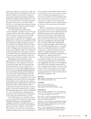
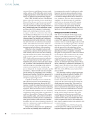
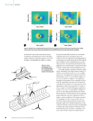
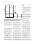
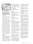
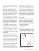
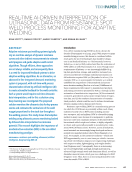
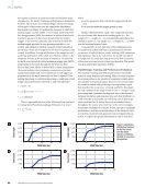
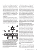
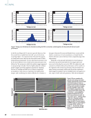
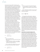
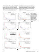
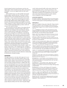
the regions of interest in ultrasonic scans and facilitate image cropping (see the Model Training and Performance Evaluation Section). The M-scans were labeled (Figure 2b) for the timing of four types of key events (see the cumulative distribution function plots in Figure 3): melting (the moment at which the molten nugget was first visible 17 102 events) steel-steel inter- face disappearance (SSID the moment at which all steel-steel interfaces appeared to have been breached by the molten nugget 16 907 events), saturation (the moment at which the molten nugget appeared to stop growing vertically 14 500 events) and expulsions (all first moments of discontinuity in the M-scan, which were suspected to be due to expulsion 6375 events). In addition, the top and bottom of the nugget as well as the top and bottom of the stack were labeled, relative to the ultrasonic M-scan, at the moment of saturation. As observed in the M-scan, historical vertical maximum nugget size (MNS) proportional to the stack throughout the weld was then derived from these labels. To derive MNS, a linear interpolation l between melting-event timestamp to saturation-event time- stamp (horizontally) and zero to maximum overall nugget size proportional to the stack (vertically) was first computed. Given melting timestamp m, saturation timestamp s, maximum overall size proportional to the stack n, and weld timestep t: nugget l =0, if t m l = t − m _s − m × n, if m ≤ t ≤ s l =n, otherwise Then, a sigmoidal function of the following form was fitted to l using the SciPy software package (Virtanen et al. 2020): y = n _1 + e −a × t−b where a is a free parameter that controls the nugget growth rate, and b is a bias that shifts the nugget growth in time. Finally, a blend between l and y was computed such that the curve began fully linear at the melting point (i.e., the weight of l =1, weight of y =0) and ends fully sigmoidal at the saturation point (i.e., the weight of l =0, weight of y =1). MNS was the resultant blended curve. Consequently, at each time step of the welding process, the model was tasked with binary classification for the first occurrence of each of the key events: melting, SSID, saturation, and expulsion. That is, for each event, the model was tasked to output zero for every time step prior to the first occurrence of the event and one for every time step thereafter. The model was also tasked with regression of MNS. Model Design, Training, and Performance Evaluation The machine learning task defined previously is essentially many-to-many sequence processing. Many-to-many sequence processing produces any number of sequential outputs given any number of sequential inputs here, for every A-scan input the model is tasked with producing a corresponding output that describes the occurrence of events and MNS. All outputs are real numbers in the range of zero to one. A 1 ms per A-scan processing time constraint was imposed due to the required temporal resolution and response time such that feedback to a weld controller is actionable, as well as the rate of data acqui- sition such that the AI system does not accumulate latency throughout the course of a weld. Due to the severe computa- tional time constraint of 1 ms per A-scan, the aim to maximize performance, and the sequential nature of the ultrasonic data, a recurrent neural network approach was investigated. In par- ticular, to exploit the spatial information in each A-scan and ME |AI/ML Weld time (ms) Weld time (ms) Weld time (ms) Weld time (ms) 20 000 15 000 10 000 5000 0 0 100 200 300 400 20 000 15 000 10 000 5000 0 0 100 200 300 400 20 000 15 000 10 000 5000 0 0 100 200 300 400 20 000 15 000 10 000 5000 0 0 100 200 300 400 Figure 3. Cumulative distribution functions for the four events over the entire dataset: (a) melting (b) SSID (c) saturation (d) expulsion. 64 M A T E R I A L S E V A L U A T I O N • J U L Y 2 0 2 3 2307 ME July dup.indd 64 6/19/23 3:41 PM E count E count E count E count
ASNT grants non-exclusive, non-transferable license of this material to  .
All rights reserved. © ASNT 2026. To report unauthorized use, contact: customersupport@asnt.org