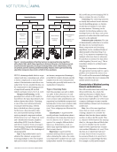
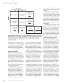
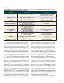
In situ measurement and monitoring techniques using various sensors and NDT methods have been extensively utilized and studied over the last few years for understanding and predicting the alterations in AM process parameters and, consequently, the quality of the manufactured parts. In situ measurement data obtained over the entire period of manufac- turing processes, combined with ex situ material characteriza- tion and information from process modeling and simulation, are essential for reducing the time and cost of process develop- ment, improving part quality, and minimizing defect formation (Hossain et al. 2022 Koester et al. 2018b). A large body of existing and rapidly growing literature is devoted to in situ monitoring methods, surveying various in situ monitoring techniques and sensors used for different types of AM processes. High-speed visible imaging (Scipioni Bertoli et al. 2017), thermography (Raplee et al. 2017), and X-ray imaging (Calta et al. 2018) are among the most used methods for in situ process monitoring for AM. Optical-based in situ monitoring methods can monitor process conditions and variations on the surface of the parts but are limited in assessing bulk material behavior. In addition, high-resolution imaging at high scanning velocities requires an external illu- mination source (Lott et al. 2011). Also, a wide range of mag- nification may be needed to cover the imaging of the entire melting pool (Lott et al. 2011). Arntz et al. (2018) analyzed the melt flow dynamics of a laser cutting process by in situ high-speed video diagnostics (100 000 fps). They showed a correlation between fluid dynamics, cutting velocity, and the average roughness of the cut flank (Arntz et al. 2018). In contrast, X-ray-based measurement methods can penetrate the materials and provide valuable information regarding the structure of the part. However, the complexity and cost of the X-ray monitoring technique and availability to most industries and manufacturers for widespread implementation of AM is a significant challenge. On the other hand, acous- tic-based techniques have been used historically for a variety of process monitoring and part qualification applications, such as in the welding process, where its rapid solidification phenomena are very similar to the AM process (Taheri 2018). Recent work has investigated the potential application of acoustic emission testing (AET) for AM processes (Koester et al. 2016, 2018a, 2019a). Accordingly, despite the type of sensing and measurement technique used for in situ AM process monitoring, analyzing the recorded dataset to identify, map, and potentially charac- terize the defects will be the next challenging step. The large dataset size and real-time processing are significant challenges in processing data for in situ measurement (Taherkhani et al. 2022). Artificial intelligence (AI) and machine learning (ML) algorithms can be promising solutions for such problems (Taheri et al. 2022). Researchers have used various supervised (Gobert et al. 2018), unsupervised (Scime and Beuth 2018), and reinforcement learning algorithms (Knaak et al. 2021) for the prediction of defects during AM processes. AI/ML methods have significant potential to improve the AM processes and the quality of manufactured parts. The T A B L E 1 A summary of common process-induced defects, their causes, and potential effects on part quality in laser metal additive manufacturing (Herzog et al. 2023) Defect type Common causes Potential effects Keyhole pores • Excessive input energy density • Reduction in mechanical properties • Reduction in fatigue properties Lack of fusion pores • Insufficient input energy density • Reduction in mechanical properties • Reduction in fatigue properties Gas pores • Gas entrapped in feedstock • Gas entrained into the melt pool • Reduction in fatigue properties Cracking and delamination • Residual stresses exceeding the local ultimate tensile strength • Insufficient bonding between layers • Part failure Deformation • Residual stresses exceeding the local yield stress • Conformance failure Alloy compositional variance • Improper powder deposition • Differing chemical mobility • Preferential evaporation • Gas incorporation/adsorption • Inhomogeneous mechanical properties Balling • Low/high input energy density • Surface oxidation • Part/conformance failure • Formation of other defects Rippling • Instabilities of layer-to-layer deposition • Part failure • Production failure Spatter/particle ejection • Overheated melt pool • Recoil pressure and melt plume • Formation of other defects J U L Y 2 0 2 3 • M A T E R I A L S E V A L U A T I O N 51 2307 ME July dup.indd 51 6/19/23 3:41 PM

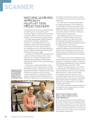
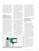
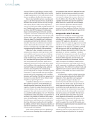
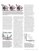
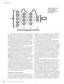
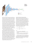
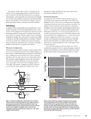
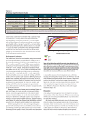
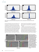
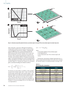
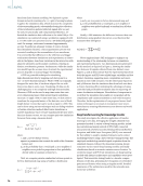
necessity of AI/ML integration to AM processes is due to the contemporary need for reduced labor cost and time, digi- tization in AM, and massive data availability (Kumar et al. 2023). AI/ML can be integrated into different sectors of man- ufacturing. In design, AI/ML increases acceptance of novel approaches and saves time and resources. In production, application of AI/ML saves time and energy and avoids waste. Finally, smart manufacturing can be interpreted as application of AI/ML in assembly processes to adjust any error in real time. Addin et al. (2007) demonstrated the potential application of ML in material science and design. In their paper, the Naïve Bayes classification is used for deterioration detection in con- struction. Jin et al. (2020) indicated that an ML model based on real-time camera images and deep learning algorithms can detect different levels of delamination conditions in FDM and determine the tendency of warping before it actually occurs. This paper aims to survey the application of AI and ML for data processing in acoustic-based in situ monitoring of AM processes. First, an overview of the acoustic emission NDT method for in situ monitoring of AM processes is presented. Then, various AI/ML techniques used by different researchers and the outcome of their analyses are described. The paper concludes with a summary of the discussion, existing chal- lenges, and potential future work. Acoustic Emission for In Situ Monitoring in AM Acoustic emission (AE), also known as acoustic emission testing (AET), as a monitoring technology has been explored by several research groups (Koester et al. 2018a Wasmer et al. 2019 Wu et al. 2016). AE refers to the generation of elastic (mechanical) waves released by materials when subjected to an external impetus, such as raising the gas pressure inside a cylinder, stim- ulating a given structure will cause deformation inside of it, such as crack growth. Consequently, this will trigger the rapid release of stored strain energy as transient elastic waves, typ- ically from a localized source. Formally, AE refers to both the generation mechanism and the waves themselves (ASTM 2020). Rapid melting and solidification occurring during the AM pro- cesses is a significant potential source of elastic waves that AE can hypothetically detect (Morales et al. 2022). Rapid generation of defects, such as cracks or porosity, can also produce elastic waves in the form of AE. A standard AE setup includes a set of piezoelectric transducers coupled to a structure, connected via cables to a monitoring system that performs data acquisition and processing. The data is stored on a computer and can be visual- ized in real time for further analysis after testing is complete. For the sake of brevity, this paper will not go into further technical details of AE fundamentals (Hossain et al. 2020). Most AE systems use a hit-based mode, which identifies transient waves in the signal and extracts features from them. A small set of parameters can describe discrete AE, which is digital (Taheri et al. 2013). The most commonly used parame- ters are rise time, peak amplitude, duration, MARSE (measured area under the rectified signal envelope) energy, and (ring- down) counts, as highlighted in Figure 1. The rise time is the time it takes for the signal to reach its peak amplitude after the first threshold crossing (defined by the operator), measured in microseconds. The duration of the hit is the time measured (usually in microseconds) from the first to the last crossing of the threshold, after which the AE hit will remain below the signal detection threshold, which the user identifies. The duration is often measured in microseconds. Given reflection and other mechanisms in a specimen, AE systems use different timing parameters to compute rise time and duration. The burst signal energy, or MARSE, is computed by taking the integral over time of the squared electrical signal over its duration. Finally, ring-down counts are the number of thresh- old crossings of an AE signal. It is another valuable parameter to help distinguish between AE signals and background noise. Combined with other signal features, some or all of these parameters can be correlated with the AM process condition through statistical signal processing and ML techniques and used to identify potential discontinuities in the manufactured parts (Bond et al. 2019 Taheri et al. 2019). For instance, Li et al. (2021) observed that the AE signals collected over a laser-cladding AM process where cracks exist in the parts have larger amplitude and energy than AE signals collected over a normal cladding process. Hossain and Taheri (2021a) discussed the potentials, limitations, and opportunities of acoustic techniques for process monitoring of AM. In this paper, the authors highlighted the capability of acoustic tech- niques for volumetric quality identification and adaptability to various manufacturing techniques as the major promising features of acoustic techniques for in situ process monitoring for AM. These abilities have been investigated in various man- ufacturing processes, including but not limited to AM, by other researchers. Ramalho et al. (2022) showed that the influence of contamination in WAAM can be identified through the analysis of the acoustic spectrum of the process. Ramalho et al. aimed to establish a microphone-based acoustic sensing method for WAAM quality monitoring. WAAM parts were fabricated with ME |AI/ML Figure 1. A burst-type AE signal and associated features (from nde-ed.org). Rise time Counts MARSE Threshold Time Duration Threshold-crossing pulses out Comparator circuit A E s i g n a l i n T h r e s h o l d i n 52 M A T E R I A L S E V A L U A T I O N • J U L Y 2 0 2 3 2307 ME July dup.indd 52 6/19/23 3:41 PM Volts Amplitude CREDIT: CNDE
ASNT grants non-exclusive, non-transferable license of this material to  .
All rights reserved. © ASNT 2026. To report unauthorized use, contact: customersupport@asnt.org