wasp–inspired designs feature compact, multi-cell configura-
tions for vertical takeoff and landing (VTOL) drones, enabling
simultaneous operations and efficient cargo storage, while also
offering better environmental shielding [8, 29, 54].
3. Drone Vertiport Design
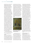
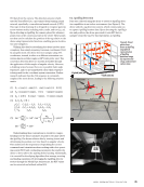
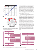
Building on insights from previous designs, a novel vertiport
system was developed inspired by the natural architecture of
trees, with “branches” serving as suspension mechanisms for
drone capsules, similar to bird nests. Solar panels mounted on
actuators at the top of the structure track the sun to maximize
energy capture, ensuring efficient and sustainable operations.
Elevated placement protects against environmental challenges
such as flooding and snow, making the design resilient in
rugged conditions like the San Juan Basin (testing site), which
experiences high winds, moisture, extreme heat, and dust.
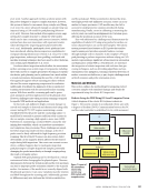
To enable autonomous drone operations, the vertiport
integrates contact-based charging, weather prediction systems,
and a central computing unit connected to a monitoring hub.
Solar panels and weather stations are positioned for optimal
functionality, while power banks and computing units at the
base ensure stability. The modular and portable design allows
deployment at multiple sites, meeting the demands of diverse
environments.
The initial test site, the San Juan Basin, required a robust
structure capable of withstanding wind speeds of up to 75 mph
(33.5 m/s) and harsh desert conditions. The system combines
lightweight, modular construction with durability, ensuring
long-term performance. The conceptual phase focused on
creating a design adaptable to severe environments while
maintaining functionality and portability. This resulted in a
versatile solution for autonomous drone operations.
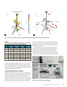
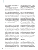
To ensure portability, the vertiport incorporates folding
telescopic features, reducing its size for transport and enabling
deployment by just two people. Leveraging existing solutions, a
satellite tower was selected as the base for its compact storage
and stable, elevated platform when deployed. This approach
minimized design and fabrication time while providing a
reliable foundation for integrating system components.
The system is designed and selected with a focus on sim-
plicity and portability, employing straightforward deployment
mechanisms and a lightweight yet sturdy aluminum frame-
work. The telescopic features of the structure enable easy
adjustments to both the trunk height and the base, enhanc-
ing adaptability in various environments. Initially, the design
included cable winches attached to the legs, anchoring them
to the top of the structure to minimize oscillation at the
maximum deployment height of approximately 27 ft (8.23 m).
However, to mitigate the risk of structural failure, the opera-
tional height was reduced to 20 ft (6.1 m). This adjustment not
only eliminates the need for a cable system, providing clearer
flight paths for the drones, but also reduces the moment arm,
improving resistance to higher wind speeds.
This structure serves as an ideal foundation for integrating
additional components of the design, most notably the capsule
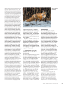
system. The initial capsule design drew inspiration from the
natural world, particularly from plants known for their endur-
ance and adaptability.
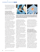
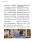
Each design concept aimed to create a secure landing
zone and sheltered housing for drones, enabling charging and
protection from environmental conditions. Two concepts—
the pitcher plant and fungi capsules—were prioritized for
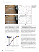
further development. The pitcher plant capsule was the first to
undergo detailed design due to its straightforward fabrication
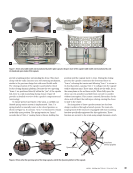
and lid actuation approach. Multiple iterations led to the final
version, depicted in Figure 1a, which became the first to be
manufactured.
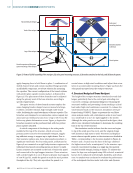
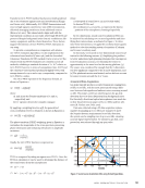
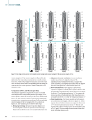
The capsule’s key feature is a dynamic platform mecha-
nism that extends when the lids open, more than doubling the
landing and takeoff areas. This design improves error tolerance
for autonomous drone landings, guiding drones to the center
as the lids close. The expandable platform also acts as the
primary actuation mechanism for the lids, using the rigidity of
the capsule shell. Figure 1b shows the CAD model and manu-
factured version of the expanding base mechanism.
The design features a lightweight aluminum 5052 H-32
shell, weighing 11.3 kg, with natural weather resistance. A
single-motor actuation system powers the capsule, using a
scissor jack mechanism to convert rotational motion from a
lead screw into vertical displacement. The stepper motor and
lead screw achieve a thrust capacity of 890 N, while custom
components enable precise movement of the scissor jack arms.
Figure 1c illustrates the actuation mechanism in open and
closed states, highlighting a high-precision track that ensures
level drone landings and reduces tilt risk.
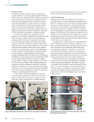
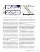
Experimental trials highlighted challenges specific to this
design’s actuation mechanism, particularly friction along the
high-tolerance tracks used to ensure precise movement of the
platform. This friction is attributed to the unique requirements
of the capsule’s expanding base mechanism, which demands
precise alignment and structural rigidity to function effectively.
While friction is a common challenge in systems requiring high
precision, the combination of dynamic loading during lid oper-
ation and the compact, lightweight construction of this design
intensified the issue. To mitigate these challenges, 3D-printed
adapters and graphite were applied to reduce friction, while
adjustments were made to address mechanical strain and motor
overload during lid descent. These observations informed the
development of a second capsule concept aimed at overcoming
these limitations and improving overall performance.
Despite these complexities, the fungi design also offered
several potential advantages over the initial concept. These
benefits theoretically included a lower drag coefficient due
to its hemispherical shape, more reliable actuation, a smaller
overall footprint, reduced lid volatility, enhanced weather-
proofing, direct lid actuation, and optimal zones for heat sink
placement. Similar to the previous design, this concept also
utilized single-motor actuation.
The dynamic platform within the capsule, as depicted
earlier, utilizes a tensioned sheet stretched across its “arms” to
ME
|
BIOINSPIREDDRONEVERTIPORTS
38
M AT E R I A L S E V A L U AT I O N • A P R I L 2 0 2 5
tions for vertical takeoff and landing (VTOL) drones, enabling
simultaneous operations and efficient cargo storage, while also
offering better environmental shielding [8, 29, 54].
3. Drone Vertiport Design
Building on insights from previous designs, a novel vertiport
system was developed inspired by the natural architecture of
trees, with “branches” serving as suspension mechanisms for
drone capsules, similar to bird nests. Solar panels mounted on
actuators at the top of the structure track the sun to maximize
energy capture, ensuring efficient and sustainable operations.
Elevated placement protects against environmental challenges
such as flooding and snow, making the design resilient in
rugged conditions like the San Juan Basin (testing site), which
experiences high winds, moisture, extreme heat, and dust.
To enable autonomous drone operations, the vertiport
integrates contact-based charging, weather prediction systems,
and a central computing unit connected to a monitoring hub.
Solar panels and weather stations are positioned for optimal
functionality, while power banks and computing units at the
base ensure stability. The modular and portable design allows
deployment at multiple sites, meeting the demands of diverse
environments.
The initial test site, the San Juan Basin, required a robust
structure capable of withstanding wind speeds of up to 75 mph
(33.5 m/s) and harsh desert conditions. The system combines
lightweight, modular construction with durability, ensuring
long-term performance. The conceptual phase focused on
creating a design adaptable to severe environments while
maintaining functionality and portability. This resulted in a
versatile solution for autonomous drone operations.
To ensure portability, the vertiport incorporates folding
telescopic features, reducing its size for transport and enabling
deployment by just two people. Leveraging existing solutions, a
satellite tower was selected as the base for its compact storage
and stable, elevated platform when deployed. This approach
minimized design and fabrication time while providing a
reliable foundation for integrating system components.
The system is designed and selected with a focus on sim-
plicity and portability, employing straightforward deployment
mechanisms and a lightweight yet sturdy aluminum frame-
work. The telescopic features of the structure enable easy
adjustments to both the trunk height and the base, enhanc-
ing adaptability in various environments. Initially, the design
included cable winches attached to the legs, anchoring them
to the top of the structure to minimize oscillation at the
maximum deployment height of approximately 27 ft (8.23 m).
However, to mitigate the risk of structural failure, the opera-
tional height was reduced to 20 ft (6.1 m). This adjustment not
only eliminates the need for a cable system, providing clearer
flight paths for the drones, but also reduces the moment arm,
improving resistance to higher wind speeds.
This structure serves as an ideal foundation for integrating
additional components of the design, most notably the capsule
system. The initial capsule design drew inspiration from the
natural world, particularly from plants known for their endur-
ance and adaptability.
Each design concept aimed to create a secure landing
zone and sheltered housing for drones, enabling charging and
protection from environmental conditions. Two concepts—
the pitcher plant and fungi capsules—were prioritized for
further development. The pitcher plant capsule was the first to
undergo detailed design due to its straightforward fabrication
and lid actuation approach. Multiple iterations led to the final
version, depicted in Figure 1a, which became the first to be
manufactured.
The capsule’s key feature is a dynamic platform mecha-
nism that extends when the lids open, more than doubling the
landing and takeoff areas. This design improves error tolerance
for autonomous drone landings, guiding drones to the center
as the lids close. The expandable platform also acts as the
primary actuation mechanism for the lids, using the rigidity of
the capsule shell. Figure 1b shows the CAD model and manu-
factured version of the expanding base mechanism.
The design features a lightweight aluminum 5052 H-32
shell, weighing 11.3 kg, with natural weather resistance. A
single-motor actuation system powers the capsule, using a
scissor jack mechanism to convert rotational motion from a
lead screw into vertical displacement. The stepper motor and
lead screw achieve a thrust capacity of 890 N, while custom
components enable precise movement of the scissor jack arms.
Figure 1c illustrates the actuation mechanism in open and
closed states, highlighting a high-precision track that ensures
level drone landings and reduces tilt risk.
Experimental trials highlighted challenges specific to this
design’s actuation mechanism, particularly friction along the
high-tolerance tracks used to ensure precise movement of the
platform. This friction is attributed to the unique requirements
of the capsule’s expanding base mechanism, which demands
precise alignment and structural rigidity to function effectively.
While friction is a common challenge in systems requiring high
precision, the combination of dynamic loading during lid oper-
ation and the compact, lightweight construction of this design
intensified the issue. To mitigate these challenges, 3D-printed
adapters and graphite were applied to reduce friction, while
adjustments were made to address mechanical strain and motor
overload during lid descent. These observations informed the
development of a second capsule concept aimed at overcoming
these limitations and improving overall performance.
Despite these complexities, the fungi design also offered
several potential advantages over the initial concept. These
benefits theoretically included a lower drag coefficient due
to its hemispherical shape, more reliable actuation, a smaller
overall footprint, reduced lid volatility, enhanced weather-
proofing, direct lid actuation, and optimal zones for heat sink
placement. Similar to the previous design, this concept also
utilized single-motor actuation.
The dynamic platform within the capsule, as depicted
earlier, utilizes a tensioned sheet stretched across its “arms” to
ME
|
BIOINSPIREDDRONEVERTIPORTS
38
M AT E R I A L S E V A L U AT I O N • A P R I L 2 0 2 5