ABSTR ACT
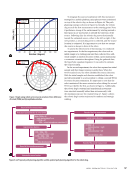
Eddy current inspection is a critical method for
assessing the health of metallic structures, but it
requires precise probe placement to avoid signal
variations caused by inconsistent liftoff. Robotic systems
enable scanning of complex geometries, maintaining
stable liftoff and ensuring accurate data collection.
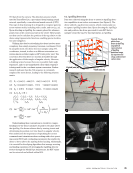
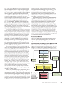
This paper presents a robotic eddy current array (ECA)
inspection system that operates without CAD models,
using computer vision to reconstruct the part’s surface
for path planning. Inaccuracies in robot calibration and
the reconstructed mesh can disrupt the probe’s precise
positioning, especially in ECA scanning, where probe
tilting increases liftoff variability, particularly at greater
distances from the tool’s center. To address these
issues, we introduce a signal processing technique that
reduces the impact of mesh inaccuracies and liftoff
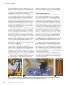
fluctuations on the acquired ECA data. The system is
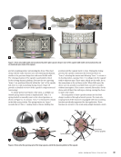
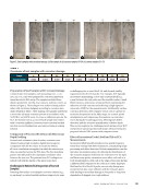
validated on curved steel samples with corrosion pits,
approximately 50 µm deep and ranging from 1 to
10 mm² in area. The results demonstrate the system’s
effectiveness in detecting defects and its potential for
integration into the NDE 4.0 framework.
KEYWORDS: robotic NDE, eddy current array, corrosion,
computer vision, part surface reconstruction, NDE 4.0
Introduction
NDE 4.0 is emerging with advancements in technology for
managing and processing large datasets, which are crucial
for verifying artificial intelligence (AI) systems that inter-
pret these datasets to determine and predict damage (Savin
et al. 2024). Various types of NDE robotic systems are being
considered for NDE 4.0, including robotic arms and mobile
platforms. Recently, several advancements have been made
in autonomous scanning of complex-shaped objects using
robotic arm platforms. Imaging and reconstruction methods,
such as hyperspectral cameras for carbon fiber solutions
(Yan et al. 2022) and X-ray for reference-free 3D scanning of
defects (Kang et al. 2022 Herl et al. 2020), have been utilized
in these systems. In the realm of robotic NDE data acquisi-
tion, advanced systems using in-process freeform scanning
via ultrasonic testing—synchronizing NDE acquisition with
path planning—have been reported (Mineo et al. 2022).
Additionally, a freeform robotic arm platform for ultrasonic
inspection of complex-shaped carbon fiber samples was
recently developed (Hamilton et al. 2024).
Historically, techniques such as laser-based profilome-
try (Doyle 1995), ultrasonic profiling (Zhen et al. 2018), and
physical touch-probes (Lee and Cho 2012) have been employed
to assess true surface geometry and adapt scans accordingly.
These methods have proven effective over decades, provid-
ing precise surface location data for applications requiring
stringent geometric fidelity. However, these approaches often
involve additional hardware complexity, require contact or
near-contact with the surface, or are less suited for large-scale
automation in NDE 4.0 applications. An example of merging
robotic systems with AI technology is the use of gripper
robotics for inspection, employing electromagnetic acoustic
transducers (EMAT) scanning and deep learning for pipe
assessment (Hespeler et al. 2024). Computer vision (CV) offers
a noncontact, scalable, and hardware-efficient alternative for
capturing and reconstructing part geometries, particularly for
complex or variable surfaces. This makes it more adaptable to
modern NDE frameworks, such as NDE 4.0, where automation,
flexibility, and integration with AI-driven systems are essential.
Recent developments in eddy current array (ECA) robotic
systems have introduced several innovative approaches. Many
of these systems utilize a rotary axis, allowing the robot to
move the ECA probe along a rotating cylindrical sample. One
such system was used for inspecting nuclear assets (Foster
ADDRESSING CHALLENGES FOR
AUTONOMOUS ROBOTIC FREEFORM EDDY
CURRENT INSPECTION VIA COMPUTER
VISION ON COMPLEX GEOMETRIES
CIARON HAMILTON†‡, OLEKSII KARPENKO†‡‡, MAHMOOD HAQ††§§, AND YIMING DENG*†§
ME
|
TECHPAPER
*Corresponding author: dengyimi@egr.msu.edu
† Department of Electrical and Computer Engineering, Michigan State
University, East Lansing, MI 48824
†† Department of Civil and Environmental Engineering, Michigan State
University, East Lansing, MI 48824
‡ ORCID: 0000-0001-9582-4843
‡‡ ORCID: 0000-0003-1146-3177
§ ORCID: 0000-0001-5958-3683
§§ ORCID: 0000-0003-2537-6015
Materials Evaluation 83 (4): 62–73
https://doi.org/10.32548/2025.me-04483
©2025 American Society for Nondestructive Testing
62
M AT E R I A L S E V A L U AT I O N • A P R I L 2 0 2 5
Eddy current inspection is a critical method for
assessing the health of metallic structures, but it
requires precise probe placement to avoid signal
variations caused by inconsistent liftoff. Robotic systems
enable scanning of complex geometries, maintaining
stable liftoff and ensuring accurate data collection.
This paper presents a robotic eddy current array (ECA)
inspection system that operates without CAD models,
using computer vision to reconstruct the part’s surface
for path planning. Inaccuracies in robot calibration and
the reconstructed mesh can disrupt the probe’s precise
positioning, especially in ECA scanning, where probe
tilting increases liftoff variability, particularly at greater
distances from the tool’s center. To address these
issues, we introduce a signal processing technique that
reduces the impact of mesh inaccuracies and liftoff
fluctuations on the acquired ECA data. The system is
validated on curved steel samples with corrosion pits,
approximately 50 µm deep and ranging from 1 to
10 mm² in area. The results demonstrate the system’s
effectiveness in detecting defects and its potential for
integration into the NDE 4.0 framework.
KEYWORDS: robotic NDE, eddy current array, corrosion,
computer vision, part surface reconstruction, NDE 4.0
Introduction
NDE 4.0 is emerging with advancements in technology for
managing and processing large datasets, which are crucial
for verifying artificial intelligence (AI) systems that inter-
pret these datasets to determine and predict damage (Savin
et al. 2024). Various types of NDE robotic systems are being
considered for NDE 4.0, including robotic arms and mobile
platforms. Recently, several advancements have been made
in autonomous scanning of complex-shaped objects using
robotic arm platforms. Imaging and reconstruction methods,
such as hyperspectral cameras for carbon fiber solutions
(Yan et al. 2022) and X-ray for reference-free 3D scanning of
defects (Kang et al. 2022 Herl et al. 2020), have been utilized
in these systems. In the realm of robotic NDE data acquisi-
tion, advanced systems using in-process freeform scanning
via ultrasonic testing—synchronizing NDE acquisition with
path planning—have been reported (Mineo et al. 2022).
Additionally, a freeform robotic arm platform for ultrasonic
inspection of complex-shaped carbon fiber samples was
recently developed (Hamilton et al. 2024).
Historically, techniques such as laser-based profilome-
try (Doyle 1995), ultrasonic profiling (Zhen et al. 2018), and
physical touch-probes (Lee and Cho 2012) have been employed
to assess true surface geometry and adapt scans accordingly.
These methods have proven effective over decades, provid-
ing precise surface location data for applications requiring
stringent geometric fidelity. However, these approaches often
involve additional hardware complexity, require contact or
near-contact with the surface, or are less suited for large-scale
automation in NDE 4.0 applications. An example of merging
robotic systems with AI technology is the use of gripper
robotics for inspection, employing electromagnetic acoustic
transducers (EMAT) scanning and deep learning for pipe
assessment (Hespeler et al. 2024). Computer vision (CV) offers
a noncontact, scalable, and hardware-efficient alternative for
capturing and reconstructing part geometries, particularly for
complex or variable surfaces. This makes it more adaptable to
modern NDE frameworks, such as NDE 4.0, where automation,
flexibility, and integration with AI-driven systems are essential.
Recent developments in eddy current array (ECA) robotic
systems have introduced several innovative approaches. Many
of these systems utilize a rotary axis, allowing the robot to
move the ECA probe along a rotating cylindrical sample. One
such system was used for inspecting nuclear assets (Foster
ADDRESSING CHALLENGES FOR
AUTONOMOUS ROBOTIC FREEFORM EDDY
CURRENT INSPECTION VIA COMPUTER
VISION ON COMPLEX GEOMETRIES
CIARON HAMILTON†‡, OLEKSII KARPENKO†‡‡, MAHMOOD HAQ††§§, AND YIMING DENG*†§
ME
|
TECHPAPER
*Corresponding author: dengyimi@egr.msu.edu
† Department of Electrical and Computer Engineering, Michigan State
University, East Lansing, MI 48824
†† Department of Civil and Environmental Engineering, Michigan State
University, East Lansing, MI 48824
‡ ORCID: 0000-0001-9582-4843
‡‡ ORCID: 0000-0003-1146-3177
§ ORCID: 0000-0001-5958-3683
§§ ORCID: 0000-0003-2537-6015
Materials Evaluation 83 (4): 62–73
https://doi.org/10.32548/2025.me-04483
©2025 American Society for Nondestructive Testing
62
M AT E R I A L S E V A L U AT I O N • A P R I L 2 0 2 5