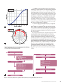
apply clamping force to hold them in place. A combination of
slotted channel struts and custom-machined hinges provides
an affordable, temporary, yet robust solution for mounting
the capsules. The current configuration of the branch system,
with pitcher plant capsule mounts in place, is illustrated in
Figure 3d. The placement of these branches can be adjusted
along the primary mast of the base structure according to
specific requirements.
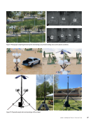
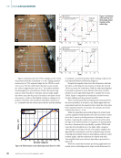
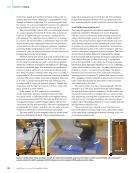
The upper section of these branch mounts employs the
same clamping bracket design however, instead of a hinge,
it utilizes a weather-resistant, high-strength multi-strand
cable, facilitating the rapid attachment of drone capsules. The
branches were designed to accommodate various capsule iter-
ations and can withstand a static force of up to 680 N (150 lb)
before any plastic deformation occurs. Figure 3c depicts the
branches mounted on the purchased hub, with two pitcher
plant capsules attached.
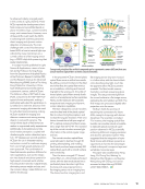
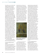
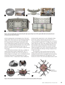
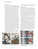
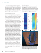
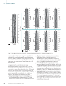
A critical component of this design is the solar panels
installed at the top of the structure, which serves as the
primary power source for the sustainable vertiport, supply-
ing sufficient energy to support up to eight drones. Due to
their extensive surface area, these solar panels are subject to
significant wind loads. The four solar panels, as illustrated in
Figure 3b, are mounted on a rigid body structure engineered to
withstand wind speeds exceeding 112 km per hour (70 mph).
Linear actuators are mounted on the back of each solar panel
and connected to the rigid support structure. These actuators,
with a stroke length of 30 cm (1 ft) and a dynamic load capacity
of 1468 N (330 lb), enable the panels to track the sun’s position
throughout the day. They also reposition the panels to a
neutral stance in high wind conditions and adjust their orien-
tation to accommodate incoming drones. Figure 3a shows the
solar panels mounted atop the vertiport structure.
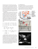
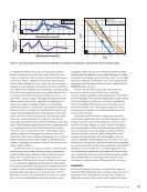
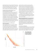
4. Structural Analysis of Drone Vertiport
The height of the vertiport structure introduced several chal-
lenges, particularly due to the central pole extending over
6 m (20 ft), creating a substantial tilting force. Ensuring the
structure’s stability and preventing it from reaching a critical
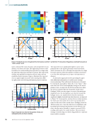
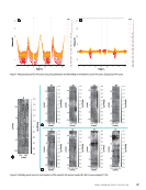
load under high wind conditions is essential. To evaluate the
wind-induced loads on the structure, simulations were per-
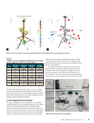
formed using COMSOL. Figure 4a presents the von Mises
stress analysis results with a deformation scale of one, based
on a wind load of 30 m/s (67 mph) applied to the model.
Although the solar panels are not depicted in the figure, their
effects were calculated beforehand to determine the resulting
load at the top of the structure.
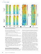
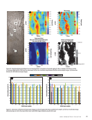
The simulation results indicate that the structure begins
to tip at this wind speed (30 m/s), and the original design
with aluminum legs starts to yield. The stress and displace-
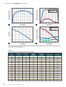
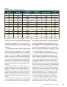
ment values at specific points on the structure are detailed in
Table 1, corresponding to the locations marked in Figure 4b.
Points 6 and 7, located near the base of the legs, exhibited
the highest stress levels, as anticipated. As the structure expe-
rienced concentrated loading on a single leg, the material
reached its yield strength, leading to failure. To address this
issue, the legs were redesigned using AISI 1018 steel, a material
known for its enhanced yield strength, durability, and robust-
ness. An analysis was conducted to evaluate the performance
of the redesigned structure under both static and dynamic
ME
|
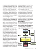
BIOINSPIREDDRONEVERTIPORTS
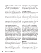
Solar panel
mounting structure
Branches attached
to the hub
Branch system
Central computer and the power
system mounting of the vertiport
Legs of the vertiport
Trunk of the vertiport
Full assembly of vertiport
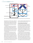
Figure 3. Views of (a) full assembly of the vertiport, (b) solar panel mounting structure, (c) branches attached to the hub, and (d) branch system.
40
M AT E R I A L S E V A L U AT I O N • A P R I L 2 0 2 5
slotted channel struts and custom-machined hinges provides
an affordable, temporary, yet robust solution for mounting
the capsules. The current configuration of the branch system,
with pitcher plant capsule mounts in place, is illustrated in
Figure 3d. The placement of these branches can be adjusted
along the primary mast of the base structure according to
specific requirements.
The upper section of these branch mounts employs the
same clamping bracket design however, instead of a hinge,
it utilizes a weather-resistant, high-strength multi-strand
cable, facilitating the rapid attachment of drone capsules. The
branches were designed to accommodate various capsule iter-
ations and can withstand a static force of up to 680 N (150 lb)
before any plastic deformation occurs. Figure 3c depicts the
branches mounted on the purchased hub, with two pitcher
plant capsules attached.
A critical component of this design is the solar panels
installed at the top of the structure, which serves as the
primary power source for the sustainable vertiport, supply-
ing sufficient energy to support up to eight drones. Due to
their extensive surface area, these solar panels are subject to
significant wind loads. The four solar panels, as illustrated in
Figure 3b, are mounted on a rigid body structure engineered to
withstand wind speeds exceeding 112 km per hour (70 mph).
Linear actuators are mounted on the back of each solar panel
and connected to the rigid support structure. These actuators,
with a stroke length of 30 cm (1 ft) and a dynamic load capacity
of 1468 N (330 lb), enable the panels to track the sun’s position
throughout the day. They also reposition the panels to a
neutral stance in high wind conditions and adjust their orien-
tation to accommodate incoming drones. Figure 3a shows the
solar panels mounted atop the vertiport structure.
4. Structural Analysis of Drone Vertiport
The height of the vertiport structure introduced several chal-
lenges, particularly due to the central pole extending over
6 m (20 ft), creating a substantial tilting force. Ensuring the
structure’s stability and preventing it from reaching a critical
load under high wind conditions is essential. To evaluate the
wind-induced loads on the structure, simulations were per-
formed using COMSOL. Figure 4a presents the von Mises
stress analysis results with a deformation scale of one, based
on a wind load of 30 m/s (67 mph) applied to the model.
Although the solar panels are not depicted in the figure, their
effects were calculated beforehand to determine the resulting
load at the top of the structure.
The simulation results indicate that the structure begins
to tip at this wind speed (30 m/s), and the original design
with aluminum legs starts to yield. The stress and displace-
ment values at specific points on the structure are detailed in
Table 1, corresponding to the locations marked in Figure 4b.
Points 6 and 7, located near the base of the legs, exhibited
the highest stress levels, as anticipated. As the structure expe-
rienced concentrated loading on a single leg, the material
reached its yield strength, leading to failure. To address this
issue, the legs were redesigned using AISI 1018 steel, a material
known for its enhanced yield strength, durability, and robust-
ness. An analysis was conducted to evaluate the performance
of the redesigned structure under both static and dynamic
ME
|
BIOINSPIREDDRONEVERTIPORTS
Solar panel
mounting structure
Branches attached
to the hub
Branch system
Central computer and the power
system mounting of the vertiport
Legs of the vertiport
Trunk of the vertiport
Full assembly of vertiport
Figure 3. Views of (a) full assembly of the vertiport, (b) solar panel mounting structure, (c) branches attached to the hub, and (d) branch system.
40
M AT E R I A L S E V A L U AT I O N • A P R I L 2 0 2 5