experimentally collected charging and discharging data for
both the power bank and drone batteries, it was estimated that
the vertiport’s power bank could support up to eight drones
continuously, along with other vertiport components.
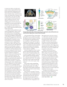
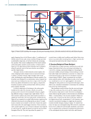
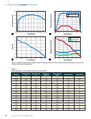
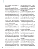
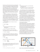
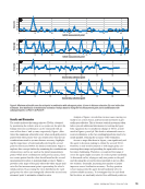
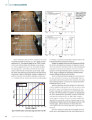
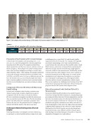
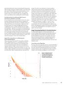
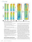
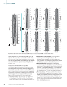
The estimation assumes that a swarm of eight drones
actively conducted surveillance tasks over a 5 h period. At
the start of the estimation at 10:00, the power bank level
was assumed to be ~50%. During this time, the solar panels
were actively generating power to charge the power bank.
After 15 min of charging (from 10:00 to 10:15) without drones
connected, the power bank level increased to 69%. At 10:15,
all eight drones returned to the vertiport with battery levels
between 10% and 15%, initiating simultaneous charging.
From 10:15 to 10:45 (30 min), the drones charged sufficiently
to conduct another 30-min surveillance task, reducing the
power bank level to ~9%. After the drones departed for their
next mission, the power bank recharged, reaching ~60% by
11:15 through the solar charging system. At this time, the drones
returned, and the process repeated. During this cycle, the
power bank level dropped from 60% to 10%.
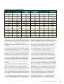
The power drop of the power bank was not consistent
throughout the process due to the solar panels providing power
to both the drone batteries and the power bank. At 1:45 p.m, the
power drop of the power bank was at its lowest (~26%), coincid-
ing with the highest power generation rate of the solar panels
due to the optimal orientation of the sun. The solar panels
operate at maximum capacity when the sun’s orientation is per-
pendicular to them. As the sun’s position changed, the power
generation rate decreased, causing the power bank’s energy
depletion rate to increase gradually. Throughout the process,
the solar panels remained horizontally aligned with the ground
surface, with no adjustments made to their orientation.
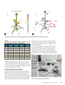
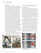
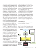
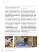
6. Drone Integration to Vertiport and Precision Landing
The drone used for this project is equipped with a flight system
that combines a flight controller and an onboard comput-
ing unit. The onboard processor handles all data collected
from the drone’s sensors and cameras and runs the necessary
software to manage communication and configuration for
flight operations. The flight controller operates with open-
source firmware, which can only be accessed via the terminal
on the onboard processor unless a direct-wired connection is
established with the flight controller’s port, typically required
only for firmware updates via image flashing.
The primary reason for selecting this drone was its high
functionality and the robust usability of its autopilot features.
These capabilities are enabled by a modular software architec-
ture running on the onboard computing unit. This architecture
consists of services, pipelines, and tools. The services include
software that handles the processing, calculation, configura-
tion, and maintenance of the drone’s individual components.
For example, the camera server manages optical input, pro-
cesses the data based on the task, and configures the cameras
for identification and filtering. Tools are used to manipulate or
inspect services, such as examining the drone’s IMU (inertia
measurement unit) servers or battery status through the PX4
software. The pipelines, a critical component of this archi-
tecture, function as data carriers between different services
that request specific information. This architecture is particu-
larly valuable to the project as it allows for the integration of
data from these pipelines into custom software applications.
An example of this architecture in action is a visual-inertial
odometry (VIO) system, which requires camera data from the
camera processing module and IMU data from the inertial
measurement unit module to calculate VIO, demonstrating the
interconnected functionality of the system.
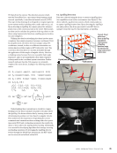
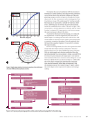
6.1. AprilTag Relocation
For landing precisely in any specific location, we use AprilTags
detected by the drones utilizing an in-built deep learning
algorithm. Building on the understanding of the drone’s
software and hardware capabilities, the focus shifts to deep
neural networks and AprilTag detection. The drone is already
equipped with software to detect and localize AprilTags using
ME
|
BIOINSPIREDDRONEVERTIPORTS
10:00 10:15 10:30 10:45 11:00 11:15 11:30 11:45 12:00 12:15
80
70
60
50
40
30
20
10
0
Time of the day (h)
12:30 12:45 13:00 13:15 13:30 13:45 14:00 14:15 14:30 14:45 15:00
Figure 7. Estimated charging pattern for eight drones.
44
M AT E R I A L S E V A L U AT I O N • A P R I L 2 0 2 5
Battery
percentage
(%)
both the power bank and drone batteries, it was estimated that
the vertiport’s power bank could support up to eight drones
continuously, along with other vertiport components.
The estimation assumes that a swarm of eight drones
actively conducted surveillance tasks over a 5 h period. At
the start of the estimation at 10:00, the power bank level
was assumed to be ~50%. During this time, the solar panels
were actively generating power to charge the power bank.
After 15 min of charging (from 10:00 to 10:15) without drones
connected, the power bank level increased to 69%. At 10:15,
all eight drones returned to the vertiport with battery levels
between 10% and 15%, initiating simultaneous charging.
From 10:15 to 10:45 (30 min), the drones charged sufficiently
to conduct another 30-min surveillance task, reducing the
power bank level to ~9%. After the drones departed for their
next mission, the power bank recharged, reaching ~60% by
11:15 through the solar charging system. At this time, the drones
returned, and the process repeated. During this cycle, the
power bank level dropped from 60% to 10%.
The power drop of the power bank was not consistent
throughout the process due to the solar panels providing power
to both the drone batteries and the power bank. At 1:45 p.m, the
power drop of the power bank was at its lowest (~26%), coincid-
ing with the highest power generation rate of the solar panels
due to the optimal orientation of the sun. The solar panels
operate at maximum capacity when the sun’s orientation is per-
pendicular to them. As the sun’s position changed, the power
generation rate decreased, causing the power bank’s energy
depletion rate to increase gradually. Throughout the process,
the solar panels remained horizontally aligned with the ground
surface, with no adjustments made to their orientation.
6. Drone Integration to Vertiport and Precision Landing
The drone used for this project is equipped with a flight system
that combines a flight controller and an onboard comput-
ing unit. The onboard processor handles all data collected
from the drone’s sensors and cameras and runs the necessary
software to manage communication and configuration for
flight operations. The flight controller operates with open-
source firmware, which can only be accessed via the terminal
on the onboard processor unless a direct-wired connection is
established with the flight controller’s port, typically required
only for firmware updates via image flashing.
The primary reason for selecting this drone was its high
functionality and the robust usability of its autopilot features.
These capabilities are enabled by a modular software architec-
ture running on the onboard computing unit. This architecture
consists of services, pipelines, and tools. The services include
software that handles the processing, calculation, configura-
tion, and maintenance of the drone’s individual components.
For example, the camera server manages optical input, pro-
cesses the data based on the task, and configures the cameras
for identification and filtering. Tools are used to manipulate or
inspect services, such as examining the drone’s IMU (inertia
measurement unit) servers or battery status through the PX4
software. The pipelines, a critical component of this archi-
tecture, function as data carriers between different services
that request specific information. This architecture is particu-
larly valuable to the project as it allows for the integration of
data from these pipelines into custom software applications.
An example of this architecture in action is a visual-inertial
odometry (VIO) system, which requires camera data from the
camera processing module and IMU data from the inertial
measurement unit module to calculate VIO, demonstrating the
interconnected functionality of the system.
6.1. AprilTag Relocation
For landing precisely in any specific location, we use AprilTags
detected by the drones utilizing an in-built deep learning
algorithm. Building on the understanding of the drone’s
software and hardware capabilities, the focus shifts to deep
neural networks and AprilTag detection. The drone is already
equipped with software to detect and localize AprilTags using
ME
|
BIOINSPIREDDRONEVERTIPORTS
10:00 10:15 10:30 10:45 11:00 11:15 11:30 11:45 12:00 12:15
80
70
60
50
40
30
20
10
0
Time of the day (h)
12:30 12:45 13:00 13:15 13:30 13:45 14:00 14:15 14:30 14:45 15:00
Figure 7. Estimated charging pattern for eight drones.
44
M AT E R I A L S E V A L U AT I O N • A P R I L 2 0 2 5
Battery
percentage
(%)