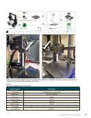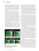
connects to a local network via Ethernet and is powered
by Power over Ethernet (PoE) through the same cable. A
wideband AE sensor was selected for its ability to withstand
higher temperatures and its small size. Specifically, it has an
operating temperature of –10 to 110 °C and a 4.75 5.8 mm size
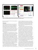
it was mounted close to the nozzle (see Figure 1b for details).
The 3D printer’s nozzle was modified to include a brass wave-
guide, placed orthogonally to the material deposition axis to
avoid high temperature effects on the AE sensor. The place-
ment of this waveguide allowed for the AE sensor’s proximity
to the heated nozzle without compromising itself or its signal
integrity. A cyanoacrylate adhesive was used as the couplant,
facilitating a robust connection between the waveguide and
the sensor.
Noise from the printer’s stepper-driven motion lies pri-
marily below ~100 Hz, well outside the operating band of the
sensor the brass waveguide further mechanically high-passes
the signal, and the DAQ applies an analog anti-aliasing filter
together with a hit-detection threshold set above the measured
electronic noise floor [10, 12, 13]. For optical data, residual
lighting variability and stray light are addressed by the YUV
histogram-equalization and HSV color-thresholding prepro-
cessing pipeline detailed in Section 2.2.
Furthermore, a camera mounted on the printer via a spe-
cially designed 3D-printed holder captured a front view of
the specimen. This arrangement was essential for real-time
observation and data collection of the specimen during the
printing process. The imaging sensor was a Raspberry Pi v2.1
camera, selected for its flexibility and Python programmability,
and mounted on the printer using a custom-printed holder.
The camera has an 8-megapixel resolution, capable of taking
images with a 3280 (h) 2662 (w) pixel count and videos at
1080p30, 720p60, and 640 × 480p90 resolutions. The current
optical layer relies on a single front-view camera multiview
imaging and registration of frames against the slicer-generated
layer blueprint (G-code) are natural extensions enabled by the
modular DEF architecture and would support feedforward cor-
rections in addition to the closed-loop (reactive) corrections
demonstrated here [9, 29, 32, 59].
The fog node (as shown in Figure 1a) represented a critical
layer in this architecture. Configured as a laptop (without loss
of generality) with a Python environment and dual network
connectivity, it ensured rapid and reliable transmission of
sensor data. Connectivity within this system was achieved
by linking the AE DAQ system to the fog node via Ethernet,
facilitating efficient data transfer and processing. This setup
was further extended to the internet to integrate with a cloud
printer controller, thereby enhancing remote control capabil-
ities and enabling real-time monitoring and correction in the
AM process. The printer controller (as shown in Figure 1a) was
OctoPrint—a versatile tool enabling remote printer manage-
ment. OctoPrint’s features, particularly its network connectivity
and control capabilities, were instrumental in managing the
3D printer remotely and ensuring efficient defect correction
within the system architecture. This integrated approach was
fundamental to enhancing the reliability and efficacy of the
AM process.
2.2. Data Acquisition and Dataset Selection
Based on this test setup, both image and acoustic datasets
were generated during the print process. To identify signal
differences between a print with no notable flaw—referred to
as “pristine”—and a print characterized by evident issues—
denoted as “defective”—print parameters such as flow rate
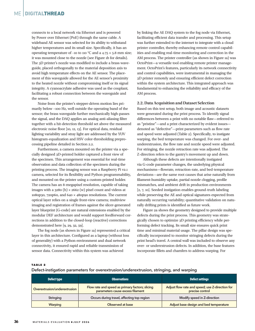
and speed were adjusted (Table 2). Specifically, to instigate
warping, the bed temperature was changed. For over- and
underextrusion, the flow rate and nozzle speed were adjusted.
For stringing, the nozzle retraction rate was adjusted. The
Z-direction refers to the gantry’s movement up and down.
Although these defects are intentionally instigated
via G-code parameter changes, the underlying physical
mechanisms—flowrate, retraction-rate, and bed-temperature
deviations—are the same root causes that arise naturally from
filament-humidity uptake, partial nozzle clogging, profile
mismatches, and ambient drift in production environments
[2, 7, 10]. Seeded instigation enables ground-truth labeling
while preserving the AE and optical signatures expected from
naturally occurring variability quantitative validation on natu-
rally drifting prints is identified as future work.
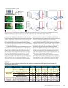
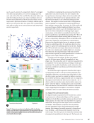
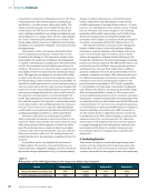
Figure 2a shows the geometry designed to provide multiple
defects during the print process. This geometry was strate-
gically chosen to optimize 3D printing efficiency while per-
forming defect tracking. Its small size ensures quick print
time and minimal material usage. The pillar design was spe-
cifically incorporated to monitor stringing defects during the
print head’s travel. A central wall was included to observe any
over- or underextrusion defects. In addition, the base features
incorporate fillets and chamfers to address warping. For
ME
|
DIGITALTHREAD
TA B L E 2
Defect-instigation parameters for overextrusion/underextrusion, stringing, and warping
Defect type Observations Defect settings
Overextrusion/underextrusion Flow rate and speed as primary factors slicing
parameters cause excess filament
Adjust flow rate and speed use Z-direction for
precise control
Stringing Occurs during travel, affecting top region Modify speed in Z-direction
Warping Observed at base Adjust base design and bed temperature
36
M AT E R I A L S E V A L U AT I O N • J U LY 2 0 2 6
by Power over Ethernet (PoE) through the same cable. A
wideband AE sensor was selected for its ability to withstand
higher temperatures and its small size. Specifically, it has an
operating temperature of –10 to 110 °C and a 4.75 5.8 mm size
it was mounted close to the nozzle (see Figure 1b for details).
The 3D printer’s nozzle was modified to include a brass wave-
guide, placed orthogonally to the material deposition axis to
avoid high temperature effects on the AE sensor. The place-
ment of this waveguide allowed for the AE sensor’s proximity
to the heated nozzle without compromising itself or its signal
integrity. A cyanoacrylate adhesive was used as the couplant,
facilitating a robust connection between the waveguide and
the sensor.
Noise from the printer’s stepper-driven motion lies pri-
marily below ~100 Hz, well outside the operating band of the
sensor the brass waveguide further mechanically high-passes
the signal, and the DAQ applies an analog anti-aliasing filter
together with a hit-detection threshold set above the measured
electronic noise floor [10, 12, 13]. For optical data, residual
lighting variability and stray light are addressed by the YUV
histogram-equalization and HSV color-thresholding prepro-
cessing pipeline detailed in Section 2.2.
Furthermore, a camera mounted on the printer via a spe-
cially designed 3D-printed holder captured a front view of
the specimen. This arrangement was essential for real-time
observation and data collection of the specimen during the
printing process. The imaging sensor was a Raspberry Pi v2.1
camera, selected for its flexibility and Python programmability,
and mounted on the printer using a custom-printed holder.
The camera has an 8-megapixel resolution, capable of taking
images with a 3280 (h) 2662 (w) pixel count and videos at
1080p30, 720p60, and 640 × 480p90 resolutions. The current
optical layer relies on a single front-view camera multiview
imaging and registration of frames against the slicer-generated
layer blueprint (G-code) are natural extensions enabled by the
modular DEF architecture and would support feedforward cor-
rections in addition to the closed-loop (reactive) corrections
demonstrated here [9, 29, 32, 59].
The fog node (as shown in Figure 1a) represented a critical
layer in this architecture. Configured as a laptop (without loss
of generality) with a Python environment and dual network
connectivity, it ensured rapid and reliable transmission of
sensor data. Connectivity within this system was achieved
by linking the AE DAQ system to the fog node via Ethernet,
facilitating efficient data transfer and processing. This setup
was further extended to the internet to integrate with a cloud
printer controller, thereby enhancing remote control capabil-
ities and enabling real-time monitoring and correction in the
AM process. The printer controller (as shown in Figure 1a) was
OctoPrint—a versatile tool enabling remote printer manage-
ment. OctoPrint’s features, particularly its network connectivity
and control capabilities, were instrumental in managing the
3D printer remotely and ensuring efficient defect correction
within the system architecture. This integrated approach was
fundamental to enhancing the reliability and efficacy of the
AM process.
2.2. Data Acquisition and Dataset Selection
Based on this test setup, both image and acoustic datasets
were generated during the print process. To identify signal
differences between a print with no notable flaw—referred to
as “pristine”—and a print characterized by evident issues—
denoted as “defective”—print parameters such as flow rate
and speed were adjusted (Table 2). Specifically, to instigate
warping, the bed temperature was changed. For over- and
underextrusion, the flow rate and nozzle speed were adjusted.
For stringing, the nozzle retraction rate was adjusted. The
Z-direction refers to the gantry’s movement up and down.
Although these defects are intentionally instigated
via G-code parameter changes, the underlying physical
mechanisms—flowrate, retraction-rate, and bed-temperature
deviations—are the same root causes that arise naturally from
filament-humidity uptake, partial nozzle clogging, profile
mismatches, and ambient drift in production environments
[2, 7, 10]. Seeded instigation enables ground-truth labeling
while preserving the AE and optical signatures expected from
naturally occurring variability quantitative validation on natu-
rally drifting prints is identified as future work.
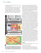
Figure 2a shows the geometry designed to provide multiple
defects during the print process. This geometry was strate-
gically chosen to optimize 3D printing efficiency while per-
forming defect tracking. Its small size ensures quick print
time and minimal material usage. The pillar design was spe-
cifically incorporated to monitor stringing defects during the
print head’s travel. A central wall was included to observe any
over- or underextrusion defects. In addition, the base features
incorporate fillets and chamfers to address warping. For
ME
|
DIGITALTHREAD
TA B L E 2
Defect-instigation parameters for overextrusion/underextrusion, stringing, and warping
Defect type Observations Defect settings
Overextrusion/underextrusion Flow rate and speed as primary factors slicing
parameters cause excess filament
Adjust flow rate and speed use Z-direction for
precise control
Stringing Occurs during travel, affecting top region Modify speed in Z-direction
Warping Observed at base Adjust base design and bed temperature
36
M AT E R I A L S E V A L U AT I O N • J U LY 2 0 2 6