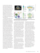
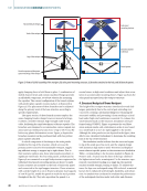
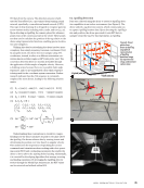
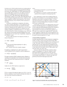
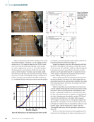
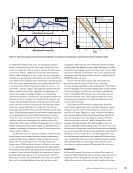
conditions, including wind loads of up to 30 m/s (~67 mph).
The new design demonstrated the ability to withstand antici-
pated environmental stresses with minimal deflection, and the
stress levels remained well below the yield strength of the steel,
ensuring overall stability and reliability.
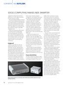
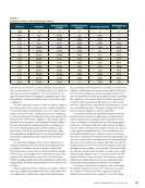
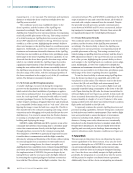
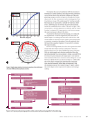
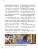
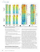
5. Power Supply of the Drone Vertiport
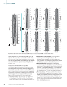
The system is designed with an isolated grid, necessitating a
renewable energy source to minimize maintenance and ensure
continuous operation (see Figure 5). Drawing inspiration
from nature, particularly how trees harness solar energy, solar
panels were chosen as the primary energy source, allowing the
vertiport to function in various environments. During daylight
hours, the solar panels will power the system, while a power
bank stores excess energy to maintain operations overnight,
ensuring the system runs continuously. Any surplus energy
generated by the panels is stored in the power bank located at
the base of the vertiport.
The energy flow within the system starts with electricity
generated by the solar panels, which then passes through a
controller. This controller regulates the voltage and current
from the solar panels, protecting the power bank from any
erratic behavior or excessive current that could cause damage.
An inverter, connected in parallel with the power bank, is used
4
109 y
z
x
y
z
x
1070
106
105
104
1030
102
2))
2
1
0
(m))
(m
))
(m
N/m2
0
4
2
1
3
2
1
0
Wind direction
–1
0
10
1108
1
10
10
1
10
((m)
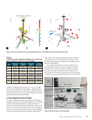
Volume: von Mises stress (N/m2)
1
2 3
4
5
6
7
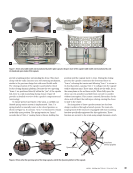
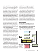
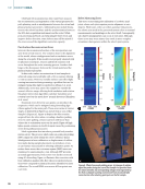
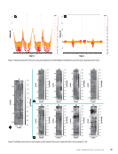
Figure 4. Views of (a) von Mises stress for gravity applied and 30 m/s wind loading, and (b) stress and displacement points.
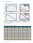
TA B L E 1
COMSOL results tabulated displacement and stress,
gravity applied, and 30 m/s wind loading
Point Displacement
in x (m)
Displacement
in y (m)
Displacement
in z (m)
von Mises
stress (N/m2)
1 4.16E-01 2.70E-01 0.12864 7.36E+05
2 2.12E-01 1.40E-01 0.1255 1.77E+06
3 2.54E-01 1.69E-01 0.2150 3.12E+06
4 –2.96E-02 –1.46E-02 0.16679 1.29E+07
5 5.81E-02 4.13E-02 0.057984 1.01E+07
6 1.99E-02 1.53E-02 0.020503 3.86E+07
7 4.61E-03 3.78E-03 0.0046386 1.46E+08
100 W
solar panel
Battery 12v/100Ah
Solar panel
controller
Drone with Skycharge
sink and contacts
Skycharge
charger and
charging pads
120v AC inverter
Figure 5. View of the system’s main isolated grid.
A P R I L 2 0 2 5 • M AT E R I A L S E V A L U AT I O N 41
The new design demonstrated the ability to withstand antici-
pated environmental stresses with minimal deflection, and the
stress levels remained well below the yield strength of the steel,
ensuring overall stability and reliability.
5. Power Supply of the Drone Vertiport
The system is designed with an isolated grid, necessitating a
renewable energy source to minimize maintenance and ensure
continuous operation (see Figure 5). Drawing inspiration
from nature, particularly how trees harness solar energy, solar
panels were chosen as the primary energy source, allowing the
vertiport to function in various environments. During daylight
hours, the solar panels will power the system, while a power
bank stores excess energy to maintain operations overnight,
ensuring the system runs continuously. Any surplus energy
generated by the panels is stored in the power bank located at
the base of the vertiport.
The energy flow within the system starts with electricity
generated by the solar panels, which then passes through a
controller. This controller regulates the voltage and current
from the solar panels, protecting the power bank from any
erratic behavior or excessive current that could cause damage.
An inverter, connected in parallel with the power bank, is used
4
109 y
z
x
y
z
x
1070
106
105
104
1030
102
2))
2
1
0
(m))
(m
))
(m
N/m2
0
4
2
1
3
2
1
0
Wind direction
–1
0
10
1108
1
10
10
1
10
((m)
Volume: von Mises stress (N/m2)
1
2 3
4
5
6
7
Figure 4. Views of (a) von Mises stress for gravity applied and 30 m/s wind loading, and (b) stress and displacement points.
TA B L E 1
COMSOL results tabulated displacement and stress,
gravity applied, and 30 m/s wind loading
Point Displacement
in x (m)
Displacement
in y (m)
Displacement
in z (m)
von Mises
stress (N/m2)
1 4.16E-01 2.70E-01 0.12864 7.36E+05
2 2.12E-01 1.40E-01 0.1255 1.77E+06
3 2.54E-01 1.69E-01 0.2150 3.12E+06
4 –2.96E-02 –1.46E-02 0.16679 1.29E+07
5 5.81E-02 4.13E-02 0.057984 1.01E+07
6 1.99E-02 1.53E-02 0.020503 3.86E+07
7 4.61E-03 3.78E-03 0.0046386 1.46E+08
100 W
solar panel
Battery 12v/100Ah
Solar panel
controller
Drone with Skycharge
sink and contacts
Skycharge
charger and
charging pads
120v AC inverter
Figure 5. View of the system’s main isolated grid.
A P R I L 2 0 2 5 • M AT E R I A L S E V A L U AT I O N 41