et al. 2022). Another approach involves a robotic system with
flex probes designed to inspect complex structures however,
this system is limited to movement along a single axis (Zhang
et al. 2020). In a more advanced example, an aircraft wing was
inspected using a CAD model for path planning (Morozov
et al. 2018). However, this method often requires reverse engi-
neering the complex structure to obtain the CAD model,
which can be time-consuming and resource intensive. Mobile
systems have also seen innovation, with repair and crawler
robots developed for inspecting power plant boilers (Shi
et al. 2021). Additionally, quadruped robotic platforms have
been introduced, offering diverse inspection capabilities for
energy-producing infrastructure (Tsenis et al. 2024). For in-line
pipe inspections, endoscopic laser profiling combined with
machine learning techniques has been used to detect deforma-
tions within pipes (Mukherjee et al. 2022).
Freeform robotic inspection methods allow for autonomous
surface scanning across a wide range of components, including
those with curved or complex geometries. By using a reconstruc-
tion device, path planning can be performed on a mesh within
a virtual environment, eliminating the need for a CAD model.
This approach supports robust scanning procedures without
the need for reverse engineering components for evaluation.
Additionally, it facilitates the alignment of the reconstructed
scanning environment with the automated surface scanning
system. With these models, a scanning path can be gener-
ated, simulated, and then implemented on the physical robot.
However, challenges arise when precision scanning is required
for specific NDE methods and applications.
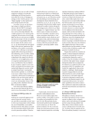
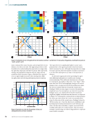
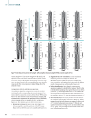
In this work, sub-millimeter depth corrosion damage on
curved steel samples is detected and characterized using eddy
current testing (ECT). ECT requires maintaining a consis-
tent liftoff between the probe and the conducting surface. A
small liftoff is essential to generate sufficient eddy currents in
the test sample, ensuring a high signal-to-noise ratio (SNR).
Furthermore, maintaining a constant liftoff is crucial for min-
imizing data variability, which can introduce uncertainties
and complicate data processing. These challenges are ampli-
fied when inspecting small corrosion damage, as the ECT
probe must be finely calibrated for high-frequency precision
scanning. The tilt of the ECT sensor can also reduce defect
detectability, as the magnetic field is affected by the sensor’s
angle during field inspections. The worst-case scenario occurs
when a collision happens due to inadequate inspection
path planning for complex-shaped test samples, potentially
damaging the probe immediately or through scraping along
the rough or irregular surface.
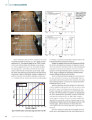
Optimal NDE path planning can be developed in a virtual
environment before being applied in physical space. However,
discrepancies between the virtual model and the test specimen
can lead to improper probe orientation relative to the scanned
surface. For instance, if the model is not correctly aligned with
the physical specimen, it can cause variations in probe rotation
and liftoff throughout the scanning path. Additionally, geomet-
ric differences may arise between the virtual reconstruction
and the actual part. While reconstruction devices like struc-
tured light provide sub-millimeter accuracy, errors can accu-
mulate for larger specimens. CAD models may also fail to
account for small geometry variations introduced during
manufacturing. Finally, errors in calibrating or mastering the
robotic joints can result in misalignments in Cartesian space,
affecting the positional accuracy of the scan.
This work addresses key challenges and demonstrates the
capabilities of robotic ECT using array probes for surface cor-
rosion characterization on curved steel samples. The robotic
system presented here features an ECA probe that enables
rapid scanning and provides expanded surface coverage
through multiple coils or channels. It also employs CV-based
path planning to perform inspections without relying on CAD
models, representing a significant advancement in automation
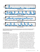
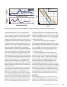
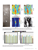
and digitization within NDE 4.0. Furthermore, we introduce
the integration of robotic inspection with real-time data pro-
cessing techniques, such as detrending algorithms and syn-
chronization error mitigation, ensuring consistent detection of
surface corrosion as shallow as 50 µm, despite challenges such
as liftoff variations and probe orientation errors.
Materials and Methods
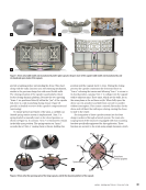
This section outlines the methodology for preparing curved
corrosion samples with simulated damage and details the
experimental setup for robotic ECA inspection.
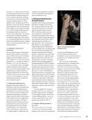
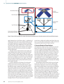
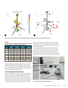
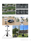
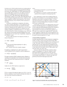
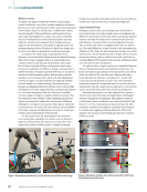
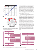
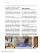
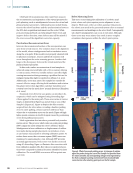
Robotic Setup for NDE Using ECA and Computer Vision
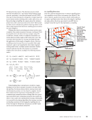
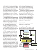
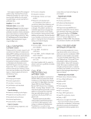
A block diagram of the robotic ECA system is shown in
Figure 1. The system consists of an industrial robotic arm with
6 degrees of freedom (DOF). Communication between the PC
and the robot controller is established via C#, with movement
PC
Robot controller
Eddy current
controller
Robot arm
Structured light
reconstruction device
Robot tool
Scanning environment
Sample
Background
Calibration marks
Calibration laser 500 kHz 32-coil
eddy current array
Laser DAQ
Figure 1. Layout of
the autonomous
robotic eddy
current array
(ECA) system with
computer vision.
A P R I L 2 0 2 5 • M AT E R I A L S E V A L U AT I O N 63
flex probes designed to inspect complex structures however,
this system is limited to movement along a single axis (Zhang
et al. 2020). In a more advanced example, an aircraft wing was
inspected using a CAD model for path planning (Morozov
et al. 2018). However, this method often requires reverse engi-
neering the complex structure to obtain the CAD model,
which can be time-consuming and resource intensive. Mobile
systems have also seen innovation, with repair and crawler
robots developed for inspecting power plant boilers (Shi
et al. 2021). Additionally, quadruped robotic platforms have
been introduced, offering diverse inspection capabilities for
energy-producing infrastructure (Tsenis et al. 2024). For in-line
pipe inspections, endoscopic laser profiling combined with
machine learning techniques has been used to detect deforma-
tions within pipes (Mukherjee et al. 2022).
Freeform robotic inspection methods allow for autonomous
surface scanning across a wide range of components, including
those with curved or complex geometries. By using a reconstruc-
tion device, path planning can be performed on a mesh within
a virtual environment, eliminating the need for a CAD model.
This approach supports robust scanning procedures without
the need for reverse engineering components for evaluation.
Additionally, it facilitates the alignment of the reconstructed
scanning environment with the automated surface scanning
system. With these models, a scanning path can be gener-
ated, simulated, and then implemented on the physical robot.
However, challenges arise when precision scanning is required
for specific NDE methods and applications.
In this work, sub-millimeter depth corrosion damage on
curved steel samples is detected and characterized using eddy
current testing (ECT). ECT requires maintaining a consis-
tent liftoff between the probe and the conducting surface. A
small liftoff is essential to generate sufficient eddy currents in
the test sample, ensuring a high signal-to-noise ratio (SNR).
Furthermore, maintaining a constant liftoff is crucial for min-
imizing data variability, which can introduce uncertainties
and complicate data processing. These challenges are ampli-
fied when inspecting small corrosion damage, as the ECT
probe must be finely calibrated for high-frequency precision
scanning. The tilt of the ECT sensor can also reduce defect
detectability, as the magnetic field is affected by the sensor’s
angle during field inspections. The worst-case scenario occurs
when a collision happens due to inadequate inspection
path planning for complex-shaped test samples, potentially
damaging the probe immediately or through scraping along
the rough or irregular surface.
Optimal NDE path planning can be developed in a virtual
environment before being applied in physical space. However,
discrepancies between the virtual model and the test specimen
can lead to improper probe orientation relative to the scanned
surface. For instance, if the model is not correctly aligned with
the physical specimen, it can cause variations in probe rotation
and liftoff throughout the scanning path. Additionally, geomet-
ric differences may arise between the virtual reconstruction
and the actual part. While reconstruction devices like struc-
tured light provide sub-millimeter accuracy, errors can accu-
mulate for larger specimens. CAD models may also fail to
account for small geometry variations introduced during
manufacturing. Finally, errors in calibrating or mastering the
robotic joints can result in misalignments in Cartesian space,
affecting the positional accuracy of the scan.
This work addresses key challenges and demonstrates the
capabilities of robotic ECT using array probes for surface cor-
rosion characterization on curved steel samples. The robotic
system presented here features an ECA probe that enables
rapid scanning and provides expanded surface coverage
through multiple coils or channels. It also employs CV-based
path planning to perform inspections without relying on CAD
models, representing a significant advancement in automation
and digitization within NDE 4.0. Furthermore, we introduce
the integration of robotic inspection with real-time data pro-
cessing techniques, such as detrending algorithms and syn-
chronization error mitigation, ensuring consistent detection of
surface corrosion as shallow as 50 µm, despite challenges such
as liftoff variations and probe orientation errors.
Materials and Methods
This section outlines the methodology for preparing curved
corrosion samples with simulated damage and details the
experimental setup for robotic ECA inspection.
Robotic Setup for NDE Using ECA and Computer Vision
A block diagram of the robotic ECA system is shown in
Figure 1. The system consists of an industrial robotic arm with
6 degrees of freedom (DOF). Communication between the PC
and the robot controller is established via C#, with movement
PC
Robot controller
Eddy current
controller
Robot arm
Structured light
reconstruction device
Robot tool
Scanning environment
Sample
Background
Calibration marks
Calibration laser 500 kHz 32-coil
eddy current array
Laser DAQ
Figure 1. Layout of
the autonomous
robotic eddy
current array
(ECA) system with
computer vision.
A P R I L 2 0 2 5 • M AT E R I A L S E V A L U AT I O N 63