capture and system intelligence such as pitch, roll,
and system pressurization levels.
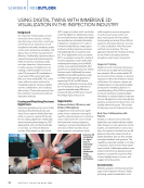
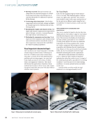
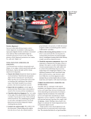
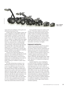
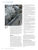
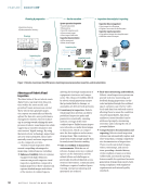
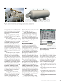
Crawler bodies are often modular in nature and
may be configured to accommodate a wide range
of assets (Figure 2). Wheeled or tracked units can
both be effective depending on the area to be tra-
versed. Access to the asset to be inspected should
also be considered, as confined launch areas, piping
geometry, or other obstacles may impact the ideal
wheel size, camera selection, or tooling configu-
ration. Vertical travel may be achieved utilizing
variable-geometry crawlers that leverage opposing
force on pipe walls, or by using vacuum-based,
magnetic-based, or magnetic-wheeled crawlers.
Each maintain certain advantages in specific appli-
cations depending on access, geometry, cleanliness,
material, contents, and line features.
Cameras and accompanying lighting are
utilized for both navigation and inspection. Ideally,
inspection cameras will offer PTZ features to
enhance data capture efforts. Advanced camera
features such as variable lighting control, aperture
manipulation, and automated weld, joint, or
feature scanning are invaluable to quality inspec-
tion efforts.
The cable reel functions as a means of com-
munication between the CCU and crawler, and
in case of an unplanned event such as a loss of
power or change in atmospheric conditions, the
safe removal of the tool. While some units may be
operated without tethers, deployment in industrial
applications typically requires a positive means of
extraction. Automated cable reels can advance and
retract the cable with the crawler movement to ease
operation and lessen the burden on the inspec-
tion team. Care should be taken with cable tending
when the crawler is navigating around obstacles
so as not to destabilize the unit. Excessive slack or
tension may inadvertently overturn the crawler.
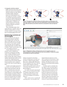
Sensor payloads for inspection crawlers can be
extensive. Tremendous industry investment has
accelerated the advancement of remote operation
tooling. Common accoutrements include lidar or
laser scanning, ultrasonics, eddy current, radiogra-
phy, and cleaning apparatuses or nozzles to facili-
tate hydrolazing (high-pressure water jetting) or CO2
cleaning. Deployment of these tools and the asso-
ciated cables and/or hoses may constrain crawler
functionality, travel distance, and agility.
Deployment Considerations
Crawler selection should be suited for the mission
objectives, inspection specifications, and line/
asset features. Mission objectives should define the
purpose and work scope. Key mission parameters
may include distance to be traveled, what data is
to be collected, and what method of testing is to be
completed. Inspection specifications will under-
score the applicable codes and standards to be
utilized. Collectively, this information shapes equip-
ment selection, technician suitability based on nec-
essary experience or certifications, and inspection
team makeup.
Operators should use care in evaluating the
access point location, orientation, and obstacles
for insertion. Common line feature considerations
include pipe geometry such as the number of
bends, bend radius, slope, and/or vertical sections
of piping system design features such as valves and
their number, location, type, and orientation and
instrumentation such as thermowells. Additionally,
obstacles such as vertical tees or downcomers to be
traversed should also be evaluated. Fabrication and
service-induced anomalies (including backing or
chill rings) and excessive line exfoliation should also
be considered. Atmospheric testing, temperature,
and cleanliness will also impact crawler selection
and mission planning.
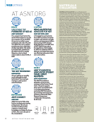
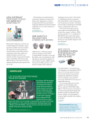
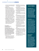
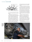
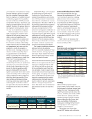
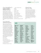
Figure 2. Modular
robotic crawler.
J U L Y 2 0 2 4 • M A T E R I A L S E V A L U A T I O N 37
CREDIT:
ENVIROSIGHT
and system pressurization levels.
Crawler bodies are often modular in nature and
may be configured to accommodate a wide range
of assets (Figure 2). Wheeled or tracked units can
both be effective depending on the area to be tra-
versed. Access to the asset to be inspected should
also be considered, as confined launch areas, piping
geometry, or other obstacles may impact the ideal
wheel size, camera selection, or tooling configu-
ration. Vertical travel may be achieved utilizing
variable-geometry crawlers that leverage opposing
force on pipe walls, or by using vacuum-based,
magnetic-based, or magnetic-wheeled crawlers.
Each maintain certain advantages in specific appli-
cations depending on access, geometry, cleanliness,
material, contents, and line features.
Cameras and accompanying lighting are
utilized for both navigation and inspection. Ideally,
inspection cameras will offer PTZ features to
enhance data capture efforts. Advanced camera
features such as variable lighting control, aperture
manipulation, and automated weld, joint, or
feature scanning are invaluable to quality inspec-
tion efforts.
The cable reel functions as a means of com-
munication between the CCU and crawler, and
in case of an unplanned event such as a loss of
power or change in atmospheric conditions, the
safe removal of the tool. While some units may be
operated without tethers, deployment in industrial
applications typically requires a positive means of
extraction. Automated cable reels can advance and
retract the cable with the crawler movement to ease
operation and lessen the burden on the inspec-
tion team. Care should be taken with cable tending
when the crawler is navigating around obstacles
so as not to destabilize the unit. Excessive slack or
tension may inadvertently overturn the crawler.
Sensor payloads for inspection crawlers can be
extensive. Tremendous industry investment has
accelerated the advancement of remote operation
tooling. Common accoutrements include lidar or
laser scanning, ultrasonics, eddy current, radiogra-
phy, and cleaning apparatuses or nozzles to facili-
tate hydrolazing (high-pressure water jetting) or CO2
cleaning. Deployment of these tools and the asso-
ciated cables and/or hoses may constrain crawler
functionality, travel distance, and agility.
Deployment Considerations
Crawler selection should be suited for the mission
objectives, inspection specifications, and line/
asset features. Mission objectives should define the
purpose and work scope. Key mission parameters
may include distance to be traveled, what data is
to be collected, and what method of testing is to be
completed. Inspection specifications will under-
score the applicable codes and standards to be
utilized. Collectively, this information shapes equip-
ment selection, technician suitability based on nec-
essary experience or certifications, and inspection
team makeup.
Operators should use care in evaluating the
access point location, orientation, and obstacles
for insertion. Common line feature considerations
include pipe geometry such as the number of
bends, bend radius, slope, and/or vertical sections
of piping system design features such as valves and
their number, location, type, and orientation and
instrumentation such as thermowells. Additionally,
obstacles such as vertical tees or downcomers to be
traversed should also be evaluated. Fabrication and
service-induced anomalies (including backing or
chill rings) and excessive line exfoliation should also
be considered. Atmospheric testing, temperature,
and cleanliness will also impact crawler selection
and mission planning.
Figure 2. Modular
robotic crawler.
J U L Y 2 0 2 4 • M A T E R I A L S E V A L U A T I O N 37
CREDIT:
ENVIROSIGHT