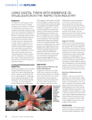
Introduction
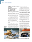
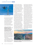
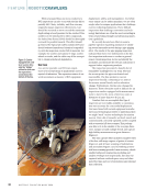
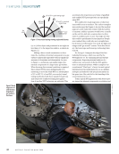
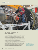
Industrial gas turbines are the heart of opera-
tions where electric power generation, cogen-
eration of electricity and steam, gas compres-
sion, propulsion in marine applications, or a
combination of these is necessary for a plant
or vessel to operate. While these turbines
are incredibly dependable, they have regular
maintenance schedules and occasionally
forced outages where remote visual inspec-
tion (RVI) is required to determine if indus-
trial gas turbines are fit for service, or if addi-
tional repairs and maintenance are required.
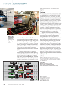
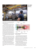
The nondestructive technique of RVI, which
is a discipline within the visual testing (VT)
method, allows for indirect visual inspections
of areas of the fan, compressor, combustion
section, and power turbine with minimal dis-
assembly. Auxiliary components and balance
of plant (BOP) items such as piping, valves,
vessels, and machinery are also inspected
with RVI during these outages. When surface
indications or discontinuities are detected,
extremely accurate indication sizing and
3D analysis are now possible with RVI. The
benefits are minimized downtime, increased
safety, and maximized return on investments
for the operation. This article provides insights
on how the proper implementation of RVI
technology, and accurate interpretation of
the data obtained during an RVI event, can
provide valuable diagnostic information on the
internal health of a gas turbine.
Direct visual examinations to determine
the safety of a situation or the quality of
assets have been around as long as eyesight.
Visual testing (VT) is thought of as a foun-
dation of nondestructive testing (NDT). VT
in industrial applications began in the early
1920s. It was not until 1988 that VT became
a certified testing method in ASNT’s SNT-
TC-1A. However, it was not widely accepted by
industry until the European Union Standards
Committee incorporated VT in the EN 473
certification standard in 2001. EN 473 was
subsequently replaced by ISO 9712:2021(en):
Nondestructive Testing – Qualification and
Certification of NDT Personnel.
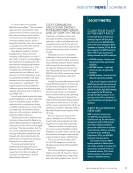
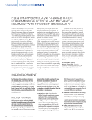
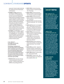
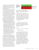
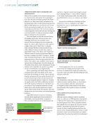
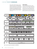
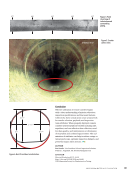
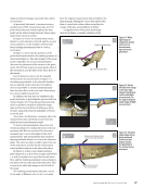
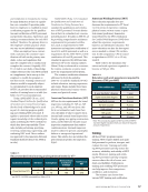
To perform effective direct visual examina-
tions, the recommended distance and angle
for viewing is to have the eye within 600 mm
60º to 90º =good viewing angle
30º to 60º =noncritical
angle of view
0º to 30º =poor
viewing angle
600 mm
(24 in.)
Test
surface
Figure 1. Direct visual testing viewing angle and
distance.
J U L Y 2 0 2 4 • M A T E R I A L S E V A L U A T I O N 41
Industrial gas turbines are the heart of opera-
tions where electric power generation, cogen-
eration of electricity and steam, gas compres-
sion, propulsion in marine applications, or a
combination of these is necessary for a plant
or vessel to operate. While these turbines
are incredibly dependable, they have regular
maintenance schedules and occasionally
forced outages where remote visual inspec-
tion (RVI) is required to determine if indus-
trial gas turbines are fit for service, or if addi-
tional repairs and maintenance are required.
The nondestructive technique of RVI, which
is a discipline within the visual testing (VT)
method, allows for indirect visual inspections
of areas of the fan, compressor, combustion
section, and power turbine with minimal dis-
assembly. Auxiliary components and balance
of plant (BOP) items such as piping, valves,
vessels, and machinery are also inspected
with RVI during these outages. When surface
indications or discontinuities are detected,
extremely accurate indication sizing and
3D analysis are now possible with RVI. The
benefits are minimized downtime, increased
safety, and maximized return on investments
for the operation. This article provides insights
on how the proper implementation of RVI
technology, and accurate interpretation of
the data obtained during an RVI event, can
provide valuable diagnostic information on the
internal health of a gas turbine.
Direct visual examinations to determine
the safety of a situation or the quality of
assets have been around as long as eyesight.
Visual testing (VT) is thought of as a foun-
dation of nondestructive testing (NDT). VT
in industrial applications began in the early
1920s. It was not until 1988 that VT became
a certified testing method in ASNT’s SNT-
TC-1A. However, it was not widely accepted by
industry until the European Union Standards
Committee incorporated VT in the EN 473
certification standard in 2001. EN 473 was
subsequently replaced by ISO 9712:2021(en):
Nondestructive Testing – Qualification and
Certification of NDT Personnel.
To perform effective direct visual examina-
tions, the recommended distance and angle
for viewing is to have the eye within 600 mm
60º to 90º =good viewing angle
30º to 60º =noncritical
angle of view
0º to 30º =poor
viewing angle
600 mm
(24 in.)
Test
surface
Figure 1. Direct visual testing viewing angle and
distance.
J U L Y 2 0 2 4 • M A T E R I A L S E V A L U A T I O N 41