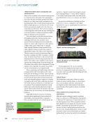
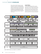
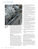
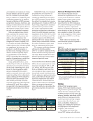
Vehicle Alignment
Safe and comfortable driving requires correct
vehicle alignment. In addition to affecting safety,
improperly aligned vehicles contribute to increased
wear and tear. This is particularly evident in
increased and uneven wear on tires. The three
primary vehicle alignment parameters are camber,
toe, and caster (Figure 13).
VISUAL INSPECTION CAPABILITIES AND
LIMITATIONS
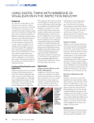
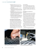
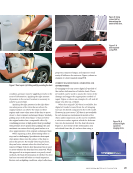
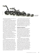
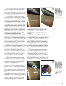
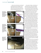
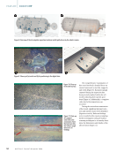
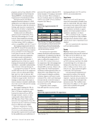
A well-trained auto mechanic using simple tools
(Figure 14) can align a vehicle using visual methods.
Following is a typical checklist used for visual
inspection for alignment.
1. Prepare the vehicle. Ensure the vehicle is parked
on a level surface. Check that the tire pressure
aligns with the manufacturer’s specifications.
Make sure there are no heavy items in the trunk
or elsewhere that could impact the vehicle’s
stance. The vehicle should be in a neutral
position, with the steering wheel centered.
2. Inspect the tire condition. Look for signs of
uneven tire wear. Uneven wear on the inside or
outside of the tires may indicate misalignment.
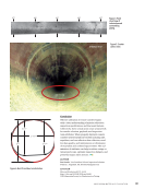
3. Check the wheel toe alignment. The “toe” refers
to the angle of the wheels relative to the vehicle’s
centerline. Stand in front of the vehicle and look
at the front wheels. They should appear parallel
to each other and aligned with the car’s body.
Repeat the process from behind the vehicle,
checking the rear wheels.
4. Examine the camber angle. The camber is the
tilt of the wheel. When looking at the vehicle
from the front or back, the wheels should be
perpendicular to the ground. A visible tilt inward
(negative camber) or outward (positive camber)
could indicate a problem.
5. Observe the steering wheel position. Sit in the
driver’s seat and check if the steering wheel is
centered when the wheels are pointed straight
ahead. A misaligned steering wheel while driving
straight can indicate alignment issues.
6. Check the suspension components. Inspect the
suspension components for any signs of wear or
damage. Worn parts can affect wheel alignment.
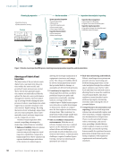
Accurate measurements of toe and camber can
be achieved by establishing reference points
using string and a straight pipe (Figure 14). Key
alignment parameters can be measured using
these reference points, a tape measure, and a
level. While the cost of the alignment tools is
minimal, the procedure largely relies on visual
inspection and requires a well-trained mechanic.
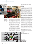
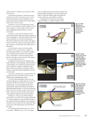
CURRENT MACHINE VISION CAPABILITIES AND
OPPORTUNITIES
Currently, there is a shortage of well-trained
mechanics, and frequent turnover at automobile
service and repair shops increases training costs
while diminishing the productivity of mechanics
employed by these businesses. For automobile
service and repair shops specializing in vehicle
alignment, tools are required to enable mechanics
with minimal training to perform the complex task
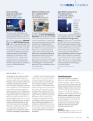
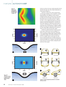
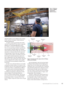
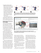
of aligning a vehicle. Machine vision–based tools
(Figure 15) automate the vehicle alignment process
and generate digital records.
Using machine vision-based alignment tools
eliminates the error associated with visual inspec-
tion. The standard deviation for a typical machine
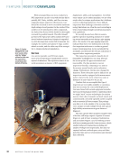
Figure 14. Visual
alignment of a
vehicle.
J U L Y 2 0 2 4 • M A T E R I A L S E V A L U A T I O N 31
Safe and comfortable driving requires correct
vehicle alignment. In addition to affecting safety,
improperly aligned vehicles contribute to increased
wear and tear. This is particularly evident in
increased and uneven wear on tires. The three
primary vehicle alignment parameters are camber,
toe, and caster (Figure 13).
VISUAL INSPECTION CAPABILITIES AND
LIMITATIONS
A well-trained auto mechanic using simple tools
(Figure 14) can align a vehicle using visual methods.
Following is a typical checklist used for visual
inspection for alignment.
1. Prepare the vehicle. Ensure the vehicle is parked
on a level surface. Check that the tire pressure
aligns with the manufacturer’s specifications.
Make sure there are no heavy items in the trunk
or elsewhere that could impact the vehicle’s
stance. The vehicle should be in a neutral
position, with the steering wheel centered.
2. Inspect the tire condition. Look for signs of
uneven tire wear. Uneven wear on the inside or
outside of the tires may indicate misalignment.
3. Check the wheel toe alignment. The “toe” refers
to the angle of the wheels relative to the vehicle’s
centerline. Stand in front of the vehicle and look
at the front wheels. They should appear parallel
to each other and aligned with the car’s body.
Repeat the process from behind the vehicle,
checking the rear wheels.
4. Examine the camber angle. The camber is the
tilt of the wheel. When looking at the vehicle
from the front or back, the wheels should be
perpendicular to the ground. A visible tilt inward
(negative camber) or outward (positive camber)
could indicate a problem.
5. Observe the steering wheel position. Sit in the
driver’s seat and check if the steering wheel is
centered when the wheels are pointed straight
ahead. A misaligned steering wheel while driving
straight can indicate alignment issues.
6. Check the suspension components. Inspect the
suspension components for any signs of wear or
damage. Worn parts can affect wheel alignment.
Accurate measurements of toe and camber can
be achieved by establishing reference points
using string and a straight pipe (Figure 14). Key
alignment parameters can be measured using
these reference points, a tape measure, and a
level. While the cost of the alignment tools is
minimal, the procedure largely relies on visual
inspection and requires a well-trained mechanic.
CURRENT MACHINE VISION CAPABILITIES AND
OPPORTUNITIES
Currently, there is a shortage of well-trained
mechanics, and frequent turnover at automobile
service and repair shops increases training costs
while diminishing the productivity of mechanics
employed by these businesses. For automobile
service and repair shops specializing in vehicle
alignment, tools are required to enable mechanics
with minimal training to perform the complex task
of aligning a vehicle. Machine vision–based tools
(Figure 15) automate the vehicle alignment process
and generate digital records.
Using machine vision-based alignment tools
eliminates the error associated with visual inspec-
tion. The standard deviation for a typical machine
Figure 14. Visual
alignment of a
vehicle.
J U L Y 2 0 2 4 • M A T E R I A L S E V A L U A T I O N 31