unplanned forced outages can result when limits
are exceeded.
As previously discussed, to increase accuracy
and precision of RVI measurement data, the XYZ
point cloud data must exactly replicate the data
points on the surface being observed. Proper place-
ment of the cursors is critical.
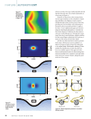
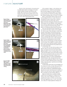
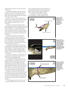
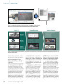
In Figure 10 we see one measurement cursor,
labeled 1, on the shroud on the left, and the second
cursor, labeled 2, on the shoulder of the far-side
stator yielding measurement data of 0.066 in.
(1.676 mm).
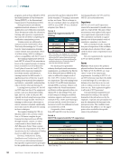
In Figure 11, notice that the geometry of the
point cloud exactly matches the surface geometry as
observed in Figure 10. The data integrity of the point
cloud would allow for accurate measurements.
Also note the placement of the cursors in the point
cloud. The RVI task requires measuring the offset of
the stator floors, not the offset of the stator floors to
the shroud.
Even if shroud-to-stator were the required
measurement, the measurement in Figure 11 is
not taken perpendicular to the shroud’s shoulder,
nor is it entirely on the stator floor. It would be
close to impossible to measure perpendicularly
from the stator floor to the next stator floor using a
two-cursor length measurement.
In addition, the data was not validated in the
point cloud prior to providing the operator with the
results. Repairs were being discussed prematurely,
which could have resulted in additional outage
days and the loss of millions of dollars per day in
revenue, along with reduced availability of electric-
ity for the grid.
Once more, this illustrates a situation where the
measurement data is perfectly accurate but also
yields incorrect measurement results.
To resolve the measurement data errors, the
technical guidance for making this stator rock mea-
surement with RVI was reviewed. The best mea-
surement type to use would again be the depth
measurement. This measurement type measures
the perpendicular distance to or from the reference
plane. The reference plane would be placed on one
of the stator floors, and the fourth measurement
cursor would be placed on the other stator floor.
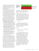
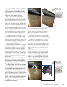
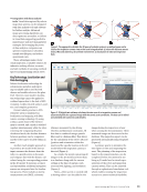
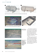
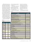
In Figure 12, a three-cursor depth reference
plane (depicted as a dotted-line triangle and labeled
1, 2, and 3) was placed on top of the far-side stator
floor, and the fourth measurement cursor, labeled 4,
was placed on top of the near-side stator floor. This
is seen in the white light image on the left half of
the image.
The resulting measurement data was 0.029 in.
(0.736 mm), a difference of 0.037 in. (0.939 mm)
from the original measurement data provided to the
plant manager. Having the correct data allowed the
plant to come back online without extending the
outage, while also saving millions of dollars.
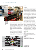
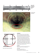
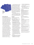
A magnified view of the point cloud image
depicted in Figure 13 enables validation of the
Top of near-side stator floor
Top of far-side stator floor
Shroud
044
BLK MTD =0.405"
0.066"
Figure 11. White
light image of
compressor section
with incorrect
measurement
type and cursor
placement.
Blade tip trailing edge
Near-side stator floor
Far-side stator floor
Shroud/air seal
1
2
3
4
A =0.066"
B =0.029"
044
BLK
MTD
A =0.405"
B =0.827"
Figure 12. On the
left side of the image
is the white light
image of compressor
section with depth
measurement. On
the right is the point
cloud image of depth
measurement.
044
BLK
MTD B =0.827"
–0.029" Measurement reference plane
cursors on far-side stator floor
Measurement cursor on
near-side stator floor
Figure 13. Full point
cloud image of area
being measured.
Point cloud data
depicts exactly
the geometry of
the surfaces being
measured.
J U L Y 2 0 2 4 • M A T E R I A L S E V A L U A T I O N 47
CREDIT:
WAYGATE
TECHNOLOGIES
CREDIT:
WAYGATE
TECHNOLOGIES
CREDIT:
WAYGATE
TECHNOLOGIES
are exceeded.
As previously discussed, to increase accuracy
and precision of RVI measurement data, the XYZ
point cloud data must exactly replicate the data
points on the surface being observed. Proper place-
ment of the cursors is critical.
In Figure 10 we see one measurement cursor,
labeled 1, on the shroud on the left, and the second
cursor, labeled 2, on the shoulder of the far-side
stator yielding measurement data of 0.066 in.
(1.676 mm).
In Figure 11, notice that the geometry of the
point cloud exactly matches the surface geometry as
observed in Figure 10. The data integrity of the point
cloud would allow for accurate measurements.
Also note the placement of the cursors in the point
cloud. The RVI task requires measuring the offset of
the stator floors, not the offset of the stator floors to
the shroud.
Even if shroud-to-stator were the required
measurement, the measurement in Figure 11 is
not taken perpendicular to the shroud’s shoulder,
nor is it entirely on the stator floor. It would be
close to impossible to measure perpendicularly
from the stator floor to the next stator floor using a
two-cursor length measurement.
In addition, the data was not validated in the
point cloud prior to providing the operator with the
results. Repairs were being discussed prematurely,
which could have resulted in additional outage
days and the loss of millions of dollars per day in
revenue, along with reduced availability of electric-
ity for the grid.
Once more, this illustrates a situation where the
measurement data is perfectly accurate but also
yields incorrect measurement results.
To resolve the measurement data errors, the
technical guidance for making this stator rock mea-
surement with RVI was reviewed. The best mea-
surement type to use would again be the depth
measurement. This measurement type measures
the perpendicular distance to or from the reference
plane. The reference plane would be placed on one
of the stator floors, and the fourth measurement
cursor would be placed on the other stator floor.
In Figure 12, a three-cursor depth reference
plane (depicted as a dotted-line triangle and labeled
1, 2, and 3) was placed on top of the far-side stator
floor, and the fourth measurement cursor, labeled 4,
was placed on top of the near-side stator floor. This
is seen in the white light image on the left half of
the image.
The resulting measurement data was 0.029 in.
(0.736 mm), a difference of 0.037 in. (0.939 mm)
from the original measurement data provided to the
plant manager. Having the correct data allowed the
plant to come back online without extending the
outage, while also saving millions of dollars.
A magnified view of the point cloud image
depicted in Figure 13 enables validation of the
Top of near-side stator floor
Top of far-side stator floor
Shroud
044
BLK MTD =0.405"
0.066"
Figure 11. White
light image of
compressor section
with incorrect
measurement
type and cursor
placement.
Blade tip trailing edge
Near-side stator floor
Far-side stator floor
Shroud/air seal
1
2
3
4
A =0.066"
B =0.029"
044
BLK
MTD
A =0.405"
B =0.827"
Figure 12. On the
left side of the image
is the white light
image of compressor
section with depth
measurement. On
the right is the point
cloud image of depth
measurement.
044
BLK
MTD B =0.827"
–0.029" Measurement reference plane
cursors on far-side stator floor
Measurement cursor on
near-side stator floor
Figure 13. Full point
cloud image of area
being measured.
Point cloud data
depicts exactly
the geometry of
the surfaces being
measured.
J U L Y 2 0 2 4 • M A T E R I A L S E V A L U A T I O N 47
CREDIT:
WAYGATE
TECHNOLOGIES
CREDIT:
WAYGATE
TECHNOLOGIES
CREDIT:
WAYGATE
TECHNOLOGIES