Results and Discussion
The comprehensive test conducted on
the vessel, coupled with a direct compar-
ison with a manual inspection carried
out by an inspector entering the vessel,
met the requested standards for inspec-
tion quality. The creation of a digital
twin streamlined the handling and
management of inspection data, facili-
tating easier analysis post-mission. The
automatic generation of the inspection
report also significantly reduced the time
required for post-inspection tasks.
The trials demonstrated that
robotics-based RVI can effectively
detect various damage mechanisms in
vessel shells and internal structures.
However, factors such as lighting angles,
camera positions, and automated
settings can impact image quality and
the detectability of pitting. Localized
pitting detection with zero-degree
ultrasonic inspection proves ineffec-
tive in heavily corroded vessels, with
external ultrasonic testing showing
greater success. RVI, structured light,
and stereoscopic imaging can measure
anomaly width, length, and depth,
although the accuracy may vary
depending on inspection conditions.
Vessel cleanliness plays a crucial role
in achieving optimal inspection results,
and while high coverage is attainable,
it relies on the inspector’s estimation.
Although calibration charts may aid in
assessing camera performance, their
direct correlation with overall inspection
effectiveness remains unclear. Utilizing
a plastic test piece offers a cost-effective
method to validate RVI capabilities, and
the integration of 3D mini-digital twins
enhances reporting compared to tradi-
tional PDF formats.
For more detailed information on the
conducted test and comprehensive results
analysis, refer to the HOIS report “HOIS-R-
070 C20-03 RII Practical Trials Report” [3].
Conclusion
In summary, the benefits of using
robotic visual inspection for confined
spaces in industry include:
Ñ High-quality, reproducible inspec-
tion data tagged with the asset’s
position and stored in a database.
Ñ A 3D virtual model tagged with
inspection data, known as a “digital
twin,” which serves as an IoT (Internet
of Things) building block and supports
digital integration strategies (such
as asset performance management
systems and data analytics). The
digital twin acts as the front end for
these tools, allowing for comparison of
repeat inspections with previous ones
to calculate trends and predictions.
Ñ Reduced outage time and costs
through offline preparation using
virtual planning and training. Safe
and simple operation of the robotic
tools is supported by full 3D spatial
awareness and 3D interactive control,
along with automatic inspection report
generation.
Ñ Process improvement through task
automation (such as automatically
repeating missions) and autopilot
functionality, enabling inspectors to
focus more on the inspection and less
on system operation.
Ñ Increased safety by avoiding human
entry into confined spaces.
These benefits apply to both asset
owners and service companies.
AUTHORS
Ekkehard Zwicker: Waygate Technologies
ekkehard.zwicker@bakerhughes.com
Brandon DeBoer: Waygate Technologies
brandon.deboer@bakerhughes.com
Markus Weissmann: Waygate Technologies
markus.weissmann@bakerhughes.com
Antoine Chevaleyre: Waygate Technologies
antoine.chevaleyre@bakerhughes.com
CITATION
Materials Evaluation 82 (7): 49–55
https://doi.org/10.32548/2024.me-04454
©2024 American Society for Nondestructive
Testing
REFERENCES
1. “Guidelines for the Application of Robotics
for the Offline Inspection of Pressure Vessels,”
SPRINT Robotics, April 2020.
2. “SPRINT Robotics Roadmap 2021,” SPRINT
Robotics, December 2021.
3. “HOIS-R-070 C20-03 RII Practical Trials
Report,” January 2023.
4. HOIS-RP-058: Recommended Practice for
Remote Internal Inspection of Pressure Vessels,
June 2023.
5. “HOIS Guidance on Image Quality for UAV/
UAS–Based External Remote Visual Inspection
in the Oil &Gas Industry,” June 2018.
6. ASME Section V: Nondestructive Examination,
Article 9, Visual Examination.
7. BS NE IS) 17637: Non-Destructive Testing of
Welds: Visual Testing of Fusion-Welded Joints.
8. “BIKE Platform Ultra Mobile Inspection
Robot,” https://www.bakerhughes.com/
waygate-technologies/robotic-inspection/bike.
9. “Shaping the future of non-destructive testing,
together,” https://esrtechnology.com/hois/.
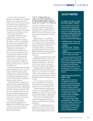
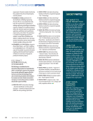
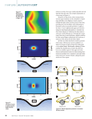
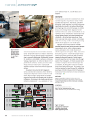
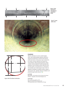
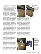
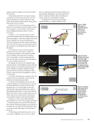
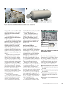
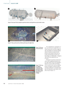
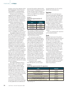
Figure 12.
Example of
a 3D surface
scan of the
shell.
J U L Y 2 0 2 4 • M A T E R I A L S E V A L U A T I O N 55
The comprehensive test conducted on
the vessel, coupled with a direct compar-
ison with a manual inspection carried
out by an inspector entering the vessel,
met the requested standards for inspec-
tion quality. The creation of a digital
twin streamlined the handling and
management of inspection data, facili-
tating easier analysis post-mission. The
automatic generation of the inspection
report also significantly reduced the time
required for post-inspection tasks.
The trials demonstrated that
robotics-based RVI can effectively
detect various damage mechanisms in
vessel shells and internal structures.
However, factors such as lighting angles,
camera positions, and automated
settings can impact image quality and
the detectability of pitting. Localized
pitting detection with zero-degree
ultrasonic inspection proves ineffec-
tive in heavily corroded vessels, with
external ultrasonic testing showing
greater success. RVI, structured light,
and stereoscopic imaging can measure
anomaly width, length, and depth,
although the accuracy may vary
depending on inspection conditions.
Vessel cleanliness plays a crucial role
in achieving optimal inspection results,
and while high coverage is attainable,
it relies on the inspector’s estimation.
Although calibration charts may aid in
assessing camera performance, their
direct correlation with overall inspection
effectiveness remains unclear. Utilizing
a plastic test piece offers a cost-effective
method to validate RVI capabilities, and
the integration of 3D mini-digital twins
enhances reporting compared to tradi-
tional PDF formats.
For more detailed information on the
conducted test and comprehensive results
analysis, refer to the HOIS report “HOIS-R-
070 C20-03 RII Practical Trials Report” [3].
Conclusion
In summary, the benefits of using
robotic visual inspection for confined
spaces in industry include:
Ñ High-quality, reproducible inspec-
tion data tagged with the asset’s
position and stored in a database.
Ñ A 3D virtual model tagged with
inspection data, known as a “digital
twin,” which serves as an IoT (Internet
of Things) building block and supports
digital integration strategies (such
as asset performance management
systems and data analytics). The
digital twin acts as the front end for
these tools, allowing for comparison of
repeat inspections with previous ones
to calculate trends and predictions.
Ñ Reduced outage time and costs
through offline preparation using
virtual planning and training. Safe
and simple operation of the robotic
tools is supported by full 3D spatial
awareness and 3D interactive control,
along with automatic inspection report
generation.
Ñ Process improvement through task
automation (such as automatically
repeating missions) and autopilot
functionality, enabling inspectors to
focus more on the inspection and less
on system operation.
Ñ Increased safety by avoiding human
entry into confined spaces.
These benefits apply to both asset
owners and service companies.
AUTHORS
Ekkehard Zwicker: Waygate Technologies
ekkehard.zwicker@bakerhughes.com
Brandon DeBoer: Waygate Technologies
brandon.deboer@bakerhughes.com
Markus Weissmann: Waygate Technologies
markus.weissmann@bakerhughes.com
Antoine Chevaleyre: Waygate Technologies
antoine.chevaleyre@bakerhughes.com
CITATION
Materials Evaluation 82 (7): 49–55
https://doi.org/10.32548/2024.me-04454
©2024 American Society for Nondestructive
Testing
REFERENCES
1. “Guidelines for the Application of Robotics
for the Offline Inspection of Pressure Vessels,”
SPRINT Robotics, April 2020.
2. “SPRINT Robotics Roadmap 2021,” SPRINT
Robotics, December 2021.
3. “HOIS-R-070 C20-03 RII Practical Trials
Report,” January 2023.
4. HOIS-RP-058: Recommended Practice for
Remote Internal Inspection of Pressure Vessels,
June 2023.
5. “HOIS Guidance on Image Quality for UAV/
UAS–Based External Remote Visual Inspection
in the Oil &Gas Industry,” June 2018.
6. ASME Section V: Nondestructive Examination,
Article 9, Visual Examination.
7. BS NE IS) 17637: Non-Destructive Testing of
Welds: Visual Testing of Fusion-Welded Joints.
8. “BIKE Platform Ultra Mobile Inspection
Robot,” https://www.bakerhughes.com/
waygate-technologies/robotic-inspection/bike.
9. “Shaping the future of non-destructive testing,
together,” https://esrtechnology.com/hois/.
Figure 12.
Example of
a 3D surface
scan of the
shell.
J U L Y 2 0 2 4 • M A T E R I A L S E V A L U A T I O N 55