image quality, it does not address safety
and operational aspects of UAV deploy-
ment, which are covered in separate
publications.
The same guidelines for an UAV-
based visual inspection can be applied
to robotic crawlers.
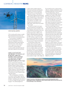
The guidance identifies three priority
applications for UAV and robotics-based
RVI among members of the HOIS orga-
nization [8]: achieving CVI resolution,
assessing coatings to ISO 4628 stan-
dards, and inspecting flare tips/stacks.
While both still images and videos are
considered, the document places more
emphasis on still images, as they are typ-
ically more common in final inspection
reports.
Specific guidance is also provided
regarding spatial resolution require-
ments for each of the priority applica-
tions, along with methods for verifying
that the achieved resolution meets these
standards. Additionally, the importance
of image signal-to-noise ratio (SNR) is
highlighted as a critical quality criterion,
with recommendations for minimum
SNR values and maximum ISO settings
for cameras. Information on these
settings can often be obtained from
resources such as the DxOMark website
or estimated based on the camera’s
sensor element area.
General advice covers various
aspects of UAV and robotics-based RVI,
including considerations for viewing
direction, ambient light levels, and
camera settings. It also addresses file
formats and post-processing software for
both still images and videos.
Overall, the document serves as
a comprehensive guide for ensuring
adequate image quality in UAV-based
RVI within the oil and gas industry. It
offers specific recommendations for key
quality criteria and priority applications
while providing general guidance on
related aspects.
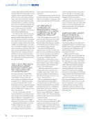
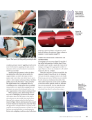
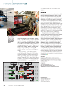
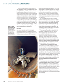
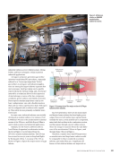
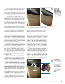
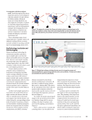
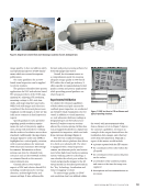
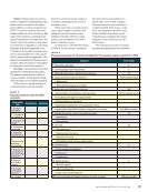
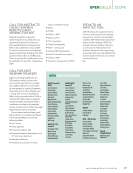
Experimental Validation
To validate the technical capabilities
of both robotics and pole cameras for
confined space inspection, we conducted
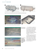
an extensive visual examination of a test
vessel. In addition to visual inspection,
we took ultrasonic thickness readings at
designated spots on the hull and con-
ducted 3D surface scans on sections
affected by corrosive pitting. All this data
was geotagged (localized) in a digital twin
optimized for inspection, which was built
from customer drawings (Figure 6).
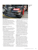
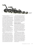
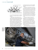
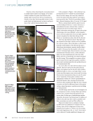
The test was conducted using an
ultra-mobile robotic platform that allows
it to climb over obstacles [8]. The robot
is equipped with a visual inspection
camera, an ultrasonic probe, and a struc-
tured white light–based surface scanning
system. Utilizing 3DLOC technology, it
can calculate the robot’s pose within the
vessel and geotag the images to the 3D
virtual model (as described previously in
the “Key Technology: Localization and
Data Geotagging” section).
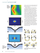
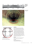
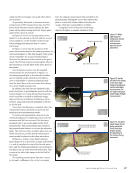
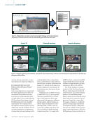
To assess image quality, an USAF
1951 resolution chart was utilized within
the vessel, with measurements taken
from a distance of 1.8 m. Figure 7 depicts
the camera’s capabilities, serving as an
example of the output obtained from the
localization data, images, and other key
notes from the inspection. Typically, a
report of this nature would include:
Ñ a picture captured with the HD camera
Ñ the coordinates of the robot within the
3D model
Ñ the coordinates of the camera hit point
on the surface
Ñ a screenshot of the crawler’s position
and stance at the time the image was
captured
Ñ descriptions and recommendations as
necessary.
Figure 6. Digital twin created from asset drawings: (a) photo of asset (b) digital twin.
Figure 7. USAF test chart at 1.8 m distance and
typical reporting structure.
J U L Y 2 0 2 4 • M A T E R I A L S E V A L U A T I O N 53
and operational aspects of UAV deploy-
ment, which are covered in separate
publications.
The same guidelines for an UAV-
based visual inspection can be applied
to robotic crawlers.
The guidance identifies three priority
applications for UAV and robotics-based
RVI among members of the HOIS orga-
nization [8]: achieving CVI resolution,
assessing coatings to ISO 4628 stan-
dards, and inspecting flare tips/stacks.
While both still images and videos are
considered, the document places more
emphasis on still images, as they are typ-
ically more common in final inspection
reports.
Specific guidance is also provided
regarding spatial resolution require-
ments for each of the priority applica-
tions, along with methods for verifying
that the achieved resolution meets these
standards. Additionally, the importance
of image signal-to-noise ratio (SNR) is
highlighted as a critical quality criterion,
with recommendations for minimum
SNR values and maximum ISO settings
for cameras. Information on these
settings can often be obtained from
resources such as the DxOMark website
or estimated based on the camera’s
sensor element area.
General advice covers various
aspects of UAV and robotics-based RVI,
including considerations for viewing
direction, ambient light levels, and
camera settings. It also addresses file
formats and post-processing software for
both still images and videos.
Overall, the document serves as
a comprehensive guide for ensuring
adequate image quality in UAV-based
RVI within the oil and gas industry. It
offers specific recommendations for key
quality criteria and priority applications
while providing general guidance on
related aspects.
Experimental Validation
To validate the technical capabilities
of both robotics and pole cameras for
confined space inspection, we conducted
an extensive visual examination of a test
vessel. In addition to visual inspection,
we took ultrasonic thickness readings at
designated spots on the hull and con-
ducted 3D surface scans on sections
affected by corrosive pitting. All this data
was geotagged (localized) in a digital twin
optimized for inspection, which was built
from customer drawings (Figure 6).
The test was conducted using an
ultra-mobile robotic platform that allows
it to climb over obstacles [8]. The robot
is equipped with a visual inspection
camera, an ultrasonic probe, and a struc-
tured white light–based surface scanning
system. Utilizing 3DLOC technology, it
can calculate the robot’s pose within the
vessel and geotag the images to the 3D
virtual model (as described previously in
the “Key Technology: Localization and
Data Geotagging” section).
To assess image quality, an USAF
1951 resolution chart was utilized within
the vessel, with measurements taken
from a distance of 1.8 m. Figure 7 depicts
the camera’s capabilities, serving as an
example of the output obtained from the
localization data, images, and other key
notes from the inspection. Typically, a
report of this nature would include:
Ñ a picture captured with the HD camera
Ñ the coordinates of the robot within the
3D model
Ñ the coordinates of the camera hit point
on the surface
Ñ a screenshot of the crawler’s position
and stance at the time the image was
captured
Ñ descriptions and recommendations as
necessary.
Figure 6. Digital twin created from asset drawings: (a) photo of asset (b) digital twin.
Figure 7. USAF test chart at 1.8 m distance and
typical reporting structure.
J U L Y 2 0 2 4 • M A T E R I A L S E V A L U A T I O N 53