A THREE-CAMERA DIGITAL IMAGE CORRELATION SYSTEM FOR FULL-FIELD 3D SHAPE AND MOTION MEASUREMENT LIKANG LUAN* AND LIAM CROSBIE† ABSTRACT A cluster-approach-based three-camera digital image correlation (DIC) system is introduced for full-field 3D shape and motion measurement. In this system, three cameras are employed to measure the same specimen area at different viewing angles. Data points within the region of interest can be evaluated by arbitrary camera pairs as a stereo DIC system so that data points with the smallest 3D residuum are selected and mapped into one common coordinate system. Two stationary shape measurements and one out-of-plane motion measurement were carried out with the three-camera DIC system. Test results were analyzed based on the same image series, projection calibration, and correlation parameters, but compared using different camera combinations (i.e., three-camera and two-camera data). Three-camera test results show not only an improved surface coverage due to the additional camera viewing angle for uneven specimen surfaces, but also a smaller and more homogenous distributed measurement uncertainty compared to the two-camera test results. The selection of data points with the smallest 3D residuum evaluated from any arbitrary camera pairs enables a better tolerance of the three-camera DIC system against various measurement error sources such as limited depth of field, lens distortion, and speckle pattern distortion due to tilted camera viewing angles. KEYWORDS: digital image correlation, DIC, multicamera, full field Introduction In the 1980s, a two-dimensional (2D) digital image correlation (DIC) technique was developed by several groups of research- ers (Peters and Ranson 1982 Sutton et al. 1983). One single camera was used to measure in-plane deformation, normally applicable to tensile testing applications of planar objects. But the measurement accuracy of 2D-DIC is influenced by artifi- cial errors caused by any out-of-plane motion toward or away from the camera, which results in a change in image projec- tion scaling (Sutton et al. 2008). In 1993, Luo et al. developed a stereoscopic DIC system by using two cameras to measure a specimen from different viewing or stereo angles, which achieved a three-dimensional (3D) measurement in subpixel accuracy, later known to be 3D-DIC or stereoscopic DIC (Luo et al. 1993). Since then, the DIC technique has gained increas- ing attention within the scientific community and has been used in various engineering applications because of its optical (non- contact) characteristic, flexibility, versatility, and measurement sensitivity (Niezrecki et al. 2010 Palanca et al. 2016 Pan 2018). Still, the stereoscopic DIC system technique has its appli- cation limitations. If the test specimen is large in size for a given focal length and camera pixel resolution, the camera field of view (FOV)—and hence working distance—must be increased, which in turn reduces the measurement resolution and sensitivity. For test components that are curved or com- plex in surface shape, blind spots may occur due to the stereo perception of the test object by the camera pair. These limitations experienced by stereoscopic DIC systems paved the way for the development of multicamera DIC. Wang et al. (2013) developed a multicamera system, which is com- posed of several conventional stereo DIC systems whereby the local individual measurement results from independent cam- era pairs were converted and stitched into a global coordinate system. Chen et al. (2013, 2014) introduced the fundamental concept of the cluster-approach-based multicamera DIC sys- tem where any two cameras can form one or more stereoscopic systems. Data points measured from different stereoscopic systems can be mapped directly into one common global coor- dinate system. Orteu et al. (2011) developed a multicamera DIC system to measure the shape variation and 3D displacement field of a sheet metal part during a single-point incremental forming operation. An improved specimen surface coverage compared to a conventional two-camera DIC system and a similar measurement accuracy as a commercial laser scan- ner system could be achieved. Malowany et al. (2017) used a * Dantec Dynamics GmbH, Ulm, Germany likang.luan@dantecdynamics.com † Dantec Dynamics GmbH, Ulm, Germany Materials Evaluation 80 (11): 34–41 https://doi.org/10.32548/2022.me-04293 ©2022 American Society for Nondestructive Testing ME | TECHNICALPAPER 34 M AT E R I A L S E V A L U AT I O N • N O V E M B E R 2 0 2 2

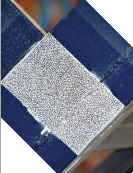
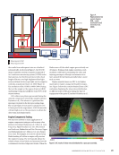
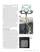
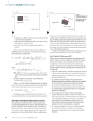
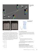
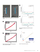
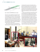
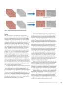
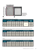
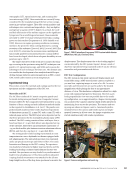
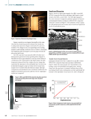
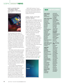
laser tracker and several stereo DIC systems simultaneously for measurements of large engineering objects with distribut- ed, nonoverlapping areas of interest. In this work, a three-camera DIC system is introduced as a transitional version between the conventional two-camera DIC system and multicamera DIC system. The same specimen area was measured from three cameras from different viewing angles and evaluated with the same cluster-approach-based DIC algorithm used in previous work (Chen et al. 2013). Instead of using a multicamera DIC system to enlarge the measurement field without losing effective pixel resolution, the basic idea of a three-camera DIC system with the same algorithm is that data points viewed from multiple camera pairs with the smallest 3D residuum (Orteu 2009) are directly applied in one global coordinate system without a stitching approach. This indicates an improved tolerance against various sources of measurement and evaluation errors for data points on the specimen area, which can be viewed from multiple camera pairs. Additionally, for test specimens with curved and uneven surface shapes, an improved surface coverage of the three-camera DIC system with the additional camera can be achieved compared to the conventional two-camera DIC system. In the following sections, the basic setup of the three-camera DIC system is introduced. Three different measurements are carried out for the first study of its per- formance compared to the test results of a conventional 3D-DIC system (i.e., two-camera DIC system). The advan- tages of the three-camera DIC system are analyzed, and its potential application is discussed. Test Setup and Methods In the three-camera DIC system shown in Figure 1, three industrial USB3 cameras are fixed on a mounting rail with two articulated mounting arms. Camera 2 is set in the center of the mounting rail and provides a direct front-on view of the specimen. Cameras 1 and 3 are fixed on the left and right sides of the mounting rail, respectively, and their positions and viewing angles can be freely adjusted. The stereo angle between each camera is set at around 35° (Ke et al. 2011 Reu 2013). The FOVs of all cameras are set as shown in Figure 1 to achieve a maximum overlapping area. Lenses measuring 23 mm are used to achieve a FOV of approximately 250 mm × 188 mm based on 1936 × 1458 pixels based on a working distance of 850 mm. One red-light LED for homogenous illumination is used in this work. A calibration target with a precisely manufactured pattern is used for the DIC system calibration procedure. Figure 2 shows the calibration target used in this study, which is a flat plate with fixed-size black and white grids. During the calibration process, the calibration target can be viewed from three cam- eras simultaneously. Eight images of the calibration targets with slightly varied angles and positions to cameras were recorded to determine all intrinsic and extrinsic parameters of the DIC system by using Zhang’s calibration method (Zhang 2000). After the calibration process, all data points (i.e., subsets or facets) on the specimen surface can be mapped into a Figure 1. Three-camera DIC system: (a) schematic (b) image. FOV for test specimen 2 1 3 Figure 2. Calibration target. N O V E M B E R 2 0 2 2 • M AT E R I A L S E V A L U AT I O N 35
ASNT grants non-exclusive, non-transferable license of this material to  .
All rights reserved. © ASNT 2026. To report unauthorized use, contact: customersupport@asnt.org