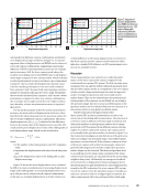
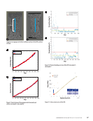
ABSTRACT Traditional nondestructive evaluation (NDE) methods present significant challenges to detecting and characterizing kissing or weak bonds in adhesively bonded structures. These kissing or weak bonds also cannot transmit shear stresses or handle complex loading modes and, if not detected, can present a significant threat to the structural integrity of the components or systems. This paper demonstrates the digital image correlation (DIC) technique for evaluating adhesively bonded dissimilar materials joints subjected to kissing or weak bonds. The study employed four adhesively bonded carbon fiber reinforced plastics and aluminum (CFRP-Al) lap-shear test coupons with varied bond quality (i.e., with no contamination and three simulated kissing bond defects). The novelty of the approach presented in this paper was that this technique could detect and demonstrate changes in the normal strain (εyy) contour map of the contaminated specimens at relatively lower load levels. This load level corresponds to 15% of the failure load for the silicone and hydraulic oil contaminated sample and around 30% for the polyvinyl alcohol (PVA) contaminated sample. In addition, higher compressive strains along the overlap edges were observed in the strain map for the single lap joints due to the higher peeling stresses of the adherend and the stress concentration at the edges of an adhesively bonded joint. KEYWORDS: DIC, kissing bond, weak bond, contamination, lap shear test, displacement, strain, stress, bond shear strength Introduction The bonding of adhesive composites to themselves or with other metal alloys offers several key advantages over traditional mechanically fastened and riveted joints. These include weight and cost savings, higher strength-to-weight ratios, fatigue and corrosion resistance, good damping characteristics, and elim- ination of the stress concentration associated with mechani- cal fasteners in loaded holes (Pocius et al. 2002 Vinson 1989). Their superior properties make them an ideal candidate for many aerospace, military, and commercial aircraft appli- cations. Some notable examples include the US Navy V-22 Osprey, US Navy F-35 Joint Strike Fighter, Boeing 787 and 777-x, and the Airbus A350 XWB, fabricated mostly of composites. Although an adhesive bonding technique offers many advantages, one of the significant limitations of this tech- nique is the occasional formation of kissing or weak bonds in the bonding interface. Kissing or weak bonds are believed to occur from many conditions, such as contamination from fuel, hydraulic, and de-icing fluids on the repair surfaces during the manufacturing process contamination of the surfaces due to environmental degradation such as water ingression and corrosion incorrect thermal cure of the adhe- sive poor mixing of the adhesive’s constituents and residual stresses, or a combination of these factors (Jeenjitkaew et al. 2010 Marty et al. 2004 Waugh et al. 2011). The bonding sur- face displays intimate mechanical contact but has little or no molecular bonding and lower adhesive strength (Guyott et al. 1986 Adams et al. 1987 Nagy 1991 Chambers and Tuck- er 1999 Brotherhood et al. 2003). It is still unclear whether these weak bonds exist and to what exact nature. However, it is widely agreed that detecting these weak and kissing bonds is crucial to the structural integrity because these interfacial bond defects could open up during peak stresses and propa- gate to a critical size before localized disbonding can produce a detectable void or structural failure in severe cases. Several researchers have reported using various NDE tech- niques to detect and characterize kissing or weak bonds in the adhesive bonds. NDE methods that are applied for the detection and quantification of kissing or weak bonds can be grouped into various ultrasonic testing methods (Nagy 1991 Chambers and Tucker 1999 Brotherhood et al. 2003 Brotherhood et al. 2002 Kundu et al. 1998 Yan et al. 2010 Yan et al. 2012 Yan et al. 2009 Bossi et al. 2002 Cerniglia et al. 2008 Ehrhart et al. 2010 Adams et al. 2011 Bossi et al. 2009 Hirsekorn 2001 Bockenheimer et al. 2002), infrared thermography (Waugh et al. 2011 Tsoi and Rajic 2011), laser shearography (Marty et al. 2004 Guo et al. 2012), ASSESSMENT OF COMPOSITE ALUMINUM ADHESIVE JOINTS USING DIGITAL IMAGE CORRELATION ANISH POUDEL* AND TSUCHIN P. CHU† * MxV Rail (formerly Transportation Technology Center Inc.), 350 Keeler Parkway, Pueblo, CO 81001 anish_poudel@aar.com † School of Mechanical, Aerospace, and Materials Engineering, Southern Illinois University, 1230 Lincoln Dr., Carbondale, IL 62901 tchu@siu.edu Materials Evaluation 80 (11): 52–61 https://doi.org/10.32548/2022.me-04281 ©2022 American Society for Nondestructive Testing ME | TECHPAPER 52 M AT E R I A L S E V A L U AT I O N • N O V E M B E R 2 0 2 2

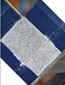
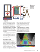
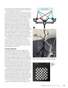
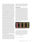
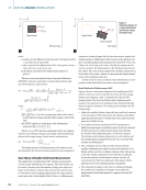
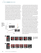
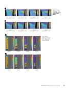
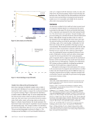
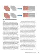
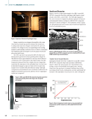
neutron radiography (Michaloudaki et al. 2005), and holographic interferometry (Heslehurst 1999). Several authors have also reported the use of varieties of experimental optical techniques, such as whole-field moiré interferometry and strain gauge techniques, for character- izing the adhesive bond properties with different levels of success and challenges (Lilleheden 1994 Tsai and Morton 1995a, 1995b Crocombe et al. 2002 Graner Solana et al. 2010 Ruiz et al. 2006 Ruiz et al. 2011). Others have reported using DIC on the adhesively bonded joints (Moutrille et al. 2009 Vijaya Kumar 2013a, 2013b Colavito et al. 2009). Moutrille et al. (2009) implemented DIC to study the effect of composite patches in Al structures. They were able to measure whole- field displacement through the thickness of a patched speci- men subjected to a tensile test. They demonstrated that shear strain decreased when the distance from the free edge of the adhesive increased, as predicted by numerical and analytical models of the joint. Vijaya Kumar et al. (2013b) investigated DIC to measure peel and shear strains in the adhesive bon- dline of CFRP-CFRP single-lap joints of varied bond quality. They also used a maximum peel stress-based failure criterion to predict failure load in healthy and degraded joints. Work presented by Colavito et al. (2009) demonstrated the feasi- bility of applying the DIC method to obtain the displacement field within the adhesive of a double-lap joint. In addition, they also showed that DIC measurements could capture a difference in the behavior of adhesively bonded double-lap joints with varying adhesive thicknesses. Similarly, work done by Moreira and Nunes (2014) was able to map shear strain distribution in flexible adhesives used for Al single-lap joints. This study aimed to investigate the application of the DIC method on adhesively bonded dissimilar materials made of CFRP-Al subjected to a wide range of kissing or weak bond defects produced by surface contamination of the CFRP sub- strate. Also, this research focused on providing a qualitative investigation of the adhesive bondline to predict whole-field strain, displacement distributions, and bond shear strength. DIC Principle The fundamental principle of DIC is based on the correlation algorithm, which uses two image data sets, typically in the form of a speckle pattern, to extract deformation profiles from tiny changes in the images. Two images—one before loading (at unde- formed state) and another during loading (at deformed state)— are used to extract deformation profiles from tiny changes in the images, which estimate displacements and strains. The correla- tion algorithm (technique) aims to find the displacements and deformations of small subsets from the second image relative to the first one, which is accomplished by comparing the intensity levels (0–255) of the subsets in the images. If the second image represents only a pure displacement, then the search is relatively simple, but if the subset is deformed due to the loading condi- tions, then the search is a little more complex. For high accuracy, the discrete gray level value of the deformed image is interpolated to obtain gray values within a pixel, followed by correlation with the subset (a small array of pixels in the undeformed image) and provides the horizontal and vertical displacement, which is used to find 2D finite strain displacements. The displacement of a subset is described by two dis- placement components of the center of the subimage, u and v, as well as four deformation gradients denoted as ∂ u ∂ x , ∂ u ∂ y , ∂ v ∂ x , ∂ v ∂ y . Two subsets are compared by calculating their cross-correlation coefficient, C, and is given by Chu et al. (1985): (1) ξ [ u, ∂ u ∂ x , ∂ u ∂ y , η [ u, ∂ u ∂ x , ∂ u ∂ y ) = C ∫ ΔM f(x, y) * (x + ξ, y + η)dA ________________________________________ [ √ ___________________________________________ ∫ ΔM (f[x, y])2 dA ∫ ΔM * (f * [x + ξ, y + η]) 2 dA ] where DM is the subset in the undeformed image, and DM* is the subset in the deformed image. (2) ξ = u + ∂ u ∂ x Δx + ∂ u ∂ y Δy (3) η = v + ∂ v ∂ x Δx + ∂ v ∂ y Δy The values of u, v, ∂u, ∂ x ∂ u ∂ y , ∂ v ∂ x , ∂ v ∂ y which maximize C, are the local deformation gradients for the selected subset. The main objective of the image correlation process is to find these six values for the subset under investigation and then repeat it for all subsets in a given region so as to find the whole-field deformation profile (Chu et al. 1985). After finding these six values of deformation gradients for all subsets in each region under investigation, the whole-field deformation profile can be generated. Experimental Methods Materials used for this study consisted of dissimilar materials: 2024-T3 aluminum and four-plies CFRP laminates. The surface of the 2024-T3 Al was prepared by sandblasting, followed by a chromic acid etching process as specified by ASTM D2651-90 (ASTM 1995). Similarly, the bonding surface of the CFRP lami- nates was prepared using the peel-ply fabric. Several lap shear panels measuring 178 mm × 229 mm were prepared, and a 25 mm wide overlap was maintained along the width of 229 mm across the bonded panel. A standard two-component epoxy system was used for the adhesive bonding between the sub- strates, and 0.2 mm glass beads were mixed into the adhesive (0.5% of resin weight) for bondline thickness control. All panels were constructed using a jig to ensure uniform pressure and constant bondline thickness, and shim-stock was used as an additional bondline thickness control measure. The jig had a bar across the top to ensure even pressure distribution in the bondline during the epoxy curing process. Four sets of samples were prepared for this work: baseline (without contamination) and three contaminated samples. The contaminants used were dry film silicone lubricant, aero- shell skydraw 41 hydraulic oil, and polyvinyl alcohol (PVA) N O V E M B E R 2 0 2 2 • M AT E R I A L S E V A L U AT I O N 53
ASNT grants non-exclusive, non-transferable license of this material to  .
All rights reserved. © ASNT 2026. To report unauthorized use, contact: customersupport@asnt.org