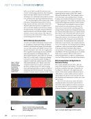
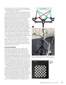
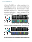
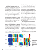
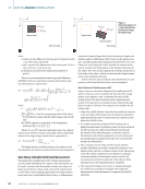
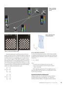
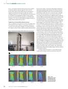
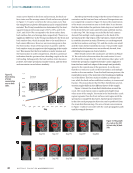
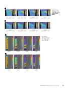
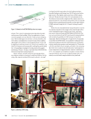
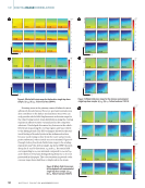
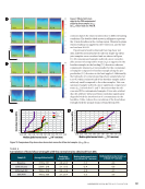
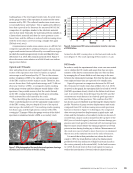
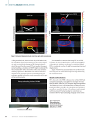
specimen from a front-left and front-right angle view with a stereo angle of around 40° to camera 2, respectively. In the sliding table measurement, a total out-of-plane displacement of 45 mm with an interval of 5 mm was set and images were taken when the specimen was completely still in different displacement stages. DIC evaluation was carried out not only with different camera combinations but also with various reference cameras, which is defined as the reference status for the facet grid generation. Figure 5c shows the facet grid generated by different reference cameras. The grid gen- erated with camera 2 as the reference camera contains 2975 data points on the specimen surface compared to the grid generated with camera 1 for 2135 data points and camera 3 for 2023 data points. The reduced data points from cameras 1 and 3 are due to their tilted viewing angles to the specimen surface, which results in a smaller projected area of the spec- imen surface to the camera FOVs. Additionally, the grids gen- erated from reference cameras 1 and 3 are inhomogeneously distributed due to the titled viewing angles. An increasing grid interval caused by the image projection, especially in the hor- izontal direction, can be observed on the specimen surface areas away from reference cameras 1 and 3. To compare the test results with different reference camer- as and camera combinations systematically, the values of the displacement total RBMR (rigid body movement removed) calculated on the whole specimen surface were compared in all test results. The displacement value of DIC measurement is a combination of the translation, rotation, and deformation of a test specimen. The rigid body motion (RBM) is defined in this work as an average motion containing only the trans- lation and rotation of the test specimen in the subsequent images compared to the reference image. This value can be determined by the following steps. First, the position of the point of gravity (POG) is calcu- lated from the whole data points on the specimen surface in both subsequent and reference images. Then, the translation of the POG in each subsequent image to the POG in the ref- erence image is calculated. After that, rotation of the contour of the test specimen at each subsequent image is carried out until its distance to the contour in the reference image is minimized. The calculated translation and rotation in the subsequent images are defined as RBM relative to the refer- ence image. Therefore, the displacement RBMR represents the deformation of a test specimen with subtracted RBM. In the sliding table measurement, only out-of-plane motion of the sliding table is applied, and no specimen deformation exists hence, the displacement total is equal to the out-of- plane motion of the sliding table in this case. Therefore, the theoretical value of displacement total RBMR should be null under ideal circumstances. The magnitude and distribution of the displacement total RBMR on the specimen surface indi- cate the magnitude of measurement error in the out-of-plane motion as the image focus deteriorates due to the influence of the depth of field (DOF). Figure 6 shows the displacement total RBMR results of the test specimen evaluated by different camera combinations and reference cameras at a max out-of- plane displacement of 45 mm. Figure 6 shows that the three-camera results contain a smaller value and more homogenous distribution of dis- placement total RBMR compared to the two-camera results, where an increasing and more inhomogeneous displacement total RBMR values up to 40 µm can be observed at the edge or corner area of the specimen. The whole specimen surface evaluated from the three-camera results shows a mean value of displacement total RBMR under 10 µm meanwhile, a simi- lar value from the two-camera results can only be found in the central area of the specimen surface. No obvious influence of reference camera selection on displacement total RBMR value and distribution can be detected, regardless of three-camera or two-camera results. Additionally, the mean values of displacement total RBMR based on the whole data points on specimen surface were Camera 1 as reference Camera 2 as reference Camera 3 as reference Result with camera 1, 2, and 3 Result with camera 1 and 2 Result with camera 1 and 3 Result with camera 2 and 3 40 µm 35 30 25 20 15 10 5 0 Figure 6. Displacement total RBMR (rigid body movement removed) plots determined at max out-of-plane displacement 45 mm evaluated by different combinations of camera groups and reference cameras. ME | DIGITALIMAGECORRELATION 38 M AT E R I A L S E V A L U AT I O N • N O V E M B E R 2 0 2 2

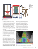
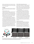
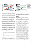
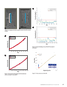
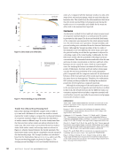
calculated from different camera combinations and plotted over displacement stages as shown in Figure 7a. An increas- ing mean value of displacement total RBMR can be observed across all camera combinations, suggesting an increasing influence of DOF on measurement accuracy as out-of-plane motion increases. Still, the three-camera result shows the smallest mean displacement total RBMR value in all displace- ment stages compared to two-camera results, which indicates a better measurement accuracy and shows a good agreement to Figure 6. The test result determined from cameras 1 and 2 shows a similar performance to the test result evaluated from cameras 2 and 3 because both camera groups contain a similar but symmetrically opposite stereo angle. Meanwhile, the test result calculated from cameras 1 and 3 shows a better performance compared to other two-camera combinations due to a larger stereo angle used in the out-of-plane motion test therefore, a better measurement accuracy is expected (Reu 2013). For the further analysis of the DIC system measurement accuracy, the mean values of displacement total were calcu- lated from the whole data points on the specimen surface for the test results of different camera combinations. The mean displacement error (dmean_error) is defined as the difference between the mean value of the displacement total of the DIC result and the preset displacement value of the sliding table at displacement stage, which can be described as: each (1) dmean_error = ∑ i=1 N i _ N − dtable where N is the number of facet data points in each DIC evaluation result, di represents the displacement total value of each data point, and dtable is the displacement value of the sliding table at each displacement stage. Figure 7b shows the mean displacement error evaluated by different camera combinations at increasing displacement stages of the sliding table. An increasing displacement error up to 180 µm can be observed in all camera combinations at the max out-of-plane displacement of 45 mm. There is no evident difference in the mean displacement error between the three-camera and two-camera results observed, which indicates a similar DOF influence on DIC measurement accu- racy in out-of-plane motion. Discussion Three measurements were carried out to study the perfor- mance of the three-camera DIC system compared to the conventional two-camera DIC system. The first two static mea- surements (the cup and the folded cardboard specimen) show that the three-camera results, in comparison to the two-camera results, provide a larger measurement area and an improved surface coverage for specimens with curved and uneven surface shapes. This can be achieved since the positions and viewing angles of the cameras can be flexibly set according to the specimen shape, then the contour and deformation of the specimen surface can be evaluated from any two cameras as a stereovision system in one global coordinate system. Further study about the improvement of the three-camera DIC system in measurement accuracy was carried out in the sliding table measurement. The selection of a reference camera influences the facet grid orientation and data point numbers on the specimen surface due to image projection on FOVs acquired from different camera viewing angles. For a three-camera DIC system, one camera can be set vertically to the specimen surface, as shown in Figure 5, so that minimized misalignment and distortion of the grid orien- tation according to the specimen shape, especially for plane specimens, can be achieved. If the reference camera is select- ed from one camera with a tilted viewing angle, a distorted grid with inhomogeneous intervals compared to specimen surface shape can be observed. This distorted grid may lead to an artificial error for strain-value calculation if the strain values of each data point are calculated from the surrounding neighbor data points. Additionally, an unexpected artificial error of contour or displacement values may appear due to the inhomogeneous grid distribution if a smoothing function is used in the DIC evaluation. For a two-camera DIC system, even if one camera views the specimen surface vertically as a reference camera to achieve an aligned grid orientation, the other camera needs still to be positioned with a tilted angle 0 0 5 10 15 20 25 5 10 15 20 Displacement stage (mm) 25 30 35 40 45 0 0 20 40 60 80 100 120 140 160 180 5 10 15 20 Displacement stage (mm) 25 30 35 40 45 Camera 1, 2, and 3 Camera 1 and 2 Camera 1 and 3 Camera 2 and 3 Camera 1, 2, and 3 Camera 1 and 2 Camera 1 and 3 Camera 2 and 3 Figure 7. Diagrams of (a) mean displacement total RBMR and (b) mean displacement error – DIC versus sliding table, evaluated by different camera combinations at increasing displacement stages. N O V E M B E R 2 0 2 2 • M AT E R I A L S E V A L U AT I O N 39 Mean displacement total RBMR (µm) Mean displacement error (µm)
ASNT grants non-exclusive, non-transferable license of this material to  .
All rights reserved. © ASNT 2026. To report unauthorized use, contact: customersupport@asnt.org