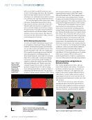
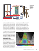
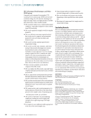
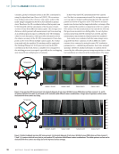
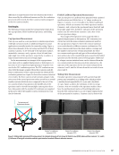
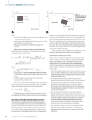
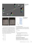
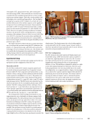
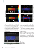
where ∆x and ∆y are the difference between point P and point Q in the x and y directions, respectively, u and v represent the displacement of the center point P in the x and y directions, respectively, and ∂ u ∂ x , ∂ u ∂ y and ∂v, ∂ x ∂v ∂ y represent the displacement gradient of point Q. The zero-mean normalized sum of squared difference (ZNSSD) criterion is selected to match subsets before and deformation, expressed as: after (3) CZNSSD( → ) = ∑ i=–M M ∑ j=–M M [ F(xi, j) − _ ______________________ √ _________________________ ∑ i=−M M j=−M[ M F(xi, j) − _ F]2 − G(xi, j ) − _ G _______________________ √ _________________________ ∑ i=−M M j=−M M [G xi, yi) − ‾ ] 2 2 where _ F = 1 _ (2M + 1)2 ∑ i=–M ∑ i=–j M F(xi,yj), _ = 1 _ (2M + 1)2 ∑ i=−M ∑ j= M G(xi,yi) are the average gray value of the subset in the reference image and the target image, respectively, and the ZNSSD criterion is a function of the deformation parameter p → u,v,∂u,∂u,∂v, ∂ x ∂ y ∂ x ∂v ∂ y ) . When CZNSSD( → ) takes the minimum value, the original subset in the reference image is matched with the deformed in the target image, which can be expressed as: subset (4) ∇ CZNSSD( → ) = [ ∂ C ∂ pi i=1,2,…,6 = 0 The displacements and deformations of the subset can be determined by the Newton iteration method to solve Equation 4. Basic Theory of Double-Sided Strain Measurement The application of multicamera DIC system measurement can be mainly divided into two aspects. First, the system can be used to measure the deformation of large area objects or large curved objects. Classic dual-camera DIC systems may not be able to meet imaging requirements for large measure- ment areas due to their limited field of view, so adding more cameras to obtain a larger field of view becomes a simple and reliable method. Multicamera DICs based on this purpose are also currently gaining many applications (Genovese et al. 2016 Chen et al. 2014 Fang et al. 2022). Second, the system can be used to measure the deformation in the thickness direction of the object. Two sets of dual-camera DIC systems are placed on both sides of the object, which can measure the displacement/ strain in the thickness direction. In this work, the front and back strain distribution of com- posites, rather than thickness strain, was investigated. Brief Method of Multicamera DIC Figure 3 shows a schematic diagram of the multicamera DIC system. Cameras 1 and 2 constitute the front 3D-DIC testing system, and cameras 3 and 4 constitute the back 3D-DIC testing system. The front and back surface displacements/ strains of the specimen are simultaneously obtained through these two pairs of systems. The main process includes the fol- lowing steps: 1. Adjust the suitable distance from the front and back cameras to the test object. With sharp focus, the distances should be approximately the same to ensure that each camera has the same size of field of view. 2. To combine the front and back 3D-DIC systems into a unified measurement coordinate system, the front and back 3D-DIC systems are calibrated simultaneously through the double-sided calibration plate, as shown in Figure 4. The intrinsic and extrinsic parameters of each camera and the transformation matrix between the two sets of 3D-DIC systems are determined. 3. The coordinate system of the 3D-DIC system with the smaller calibration error will be used as the reference coor- dinate system, and the coordinate system of the other group of 3D-DIC will be transferred to the reference coordinate system through the transformation matrix, and the 3D reconstruction of the front and back of the object will be performed once the transformation is completed. 4. The temporal 3D shape of the object is obtained through the continuous acquisition of images. Front and back displacement/strain information is computed by the DIC algorithm. ME | DIGITALIMAGECORRELATION P (x p , y p ) Q (x q , y q ) P (x´, p y´) p Q´ (x´, q y´) q Original subset Original subset o x y o x y Deformed subset Reference image Target image Figure 2. Schematic diagram of a subset deformation (a) reference image (b) target image. 44 M AT E R I A L S E V A L U AT I O N • N O V E M B E R 2 0 2 2

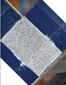
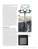
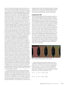
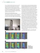
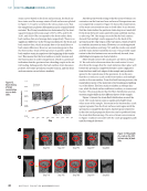
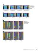
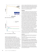
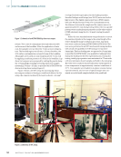
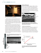
Since the measurement coordinate systems of the two groups of 3D-DIC systems are unified through the double-sid- ed calibration method, for any point O on the front surface of the object, there is a corresponding point O′ on the rear sur- face, as shown in Figure 5. This makes it possible to compare the strain histories of corresponding points on the front and back surfaces. Based on the displacement fields (u, v, w) and (u′, v ′ , w ′ of the front and back surfaces in a unified Cartesian coordinate system, the normal strains of the front and back surfaces are obtained by Equations 4 and 5: (5) ⎧ ⎪ ⎪ ⎩ εx = ∂ u ∂ x εy = ∂ v ∂ y z = ∂ w ∂ z (6) ⎧ ⎪ ⎪ ⎩ ε′ x = ∂ u′ ∂ x εy = ∂ v′ ∂ y z = ∂ w′ ∂ z Percent Bending Calculation To ensure the measurement accuracy of the Young’s modulus of composite materials from the stress-strain curve, the percent bending during the experiment needs to be evaluated, as given in Equation 7: (7) By = − εb| _ |εf |εf + εb| where By represents percent bending in the specimen, and εf and εb represent strain from the front surface and back surface, respectively. When bending is greater than 3%, averaged strain from the front surface and back surface is recommended to calcu- late the Young’s modulus. Experimental Results and Discussion Standard tensile tests were performed to measure the front and back surface strain of the specimen. The experimen- tal setup is shown in Figure 6. Four high-resolution cameras 8 mm Al-08-BDB_9 x 9_0131 8 mm Figure 4. Double-sided calibration plate. O O´ x z y Figure 5. Schematic of the corresponding points. Camera 1 Camera 2 Camera 3 Camera 4 Figure 3. Schematic of multicamera DIC system. N O V E M B E R 2 0 2 2 • M AT E R I A L S E V A L U AT I O N 45
ASNT grants non-exclusive, non-transferable license of this material to  .
All rights reserved. © ASNT 2026. To report unauthorized use, contact: customersupport@asnt.org