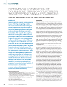
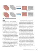
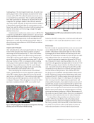
ABSTRACT Environmental barrier coatings (EBCs) are used as a coating material on fiber-reinforced ceramic matrix composites (CMC) for various aerospace and turbine engines applications. In order to validate physics- based analytical models for predicting the spallation life of EBCs, the fracture strength of the EBC and the kinetics of crack growth in EBC layers need to be experimentally determined under engine operating conditions. In this study, a coating layer of barium strontium aluminum silicate (BSAS)–based melt- infiltrated silicon carbide fiber-reinforced silicon carbide matrix composite (MI SiC/SiC) is applied on a CMC specimen and tensile tested at room temperature. Multiple tests are performed on a single specimen with increasing predetermined stress levels until final failure. Damage progression due to the load applied is monitored using a digital image correlation (DIC) system. After unloading from the predetermined stress levels, the specimen is evaluated by optical microscopy and computed tomography (CT). The inspection forms the imaging which implied that primary and secondary cracks developed during tensile loading until failure. DIC showed formation of a primary crack at ~50% of the ultimate tensile strength, and this crack grew with increasing stress and eventually led to final failure of the specimen. KEYWORDS: digital image correlation, tensile test, NDE, CMC, EBC, computed tomography Introduction Data from strain and displacement measurements are typically collected using bonded strain gauges and a string potentiom- eter, or a linear variable differential transformer (LVDT). This data is important to document the behavior of the components and characterization of the material. Using the latter devices to collect such data has been useful in acquiring the necessary data, but they have limitations in certain situations and testing conditions. For example, a single-element strain gauge will provide the strain only in the grid direction. Any displacement not in the measurement direction will not be directly obtained and, in many cases, adversely affect the actual measurement. Additionally, under certain circumstances, multiple strain gauges are needed to extract principal strains and directions. The mea- surement area of interest must be determined ahead of testing to locate the most suitable location. Such locations are deter- mined via analytical modeling, which can be not quite accurate and lead to substantial differences between the actual strain and measured strain. In addition, a clean surface area is required for strain gauge application to ensure a surface free of loose parti- cles and other material that could flake off during testing. As an alternative to these approaches, a digital image correlation (DIC) camera system can be used to avoid these types of concerns by measuring the surface displacement and strain over the entire area of interest. It is a noncontact optical technique that is capable of measuring displacement and cal- culating strain fields. Unlike typical strain gauge applications, DIC does not require a perfectly smooth surface to obtain proper measurements and can measure surfaces with a sur- face roughness of greater than RMS 420. DIC is quite simple to use and cost-effective compared to other techniques, such as speckle interferometry, as well as other commonly available techniques (Stress Engineering Services Inc. n.d.). This optical measurement technique has been proven to be a reliable non- contact method for the study of material deformation and even crack propagation (Schreier et al. 2009). DIC compares the dig- ital photographs of a component or a test specimen at various stages of deformation. Through application of image tracking and registration algorithms, 2D or 3D displacement fields are generated from which corresponding strain fields are comput- ed. For an effective outcome, the pixel blocks need to be ran- dom and unique with a range of contrast and intensity levels. In the current study, damage monitoring due to tensile loading of silicon-carbide fiber-reinforced silicon-carbide ceramic matrix composites (SiC/SiC CMC) is observed and traced using NDE techniques, which include DIC, computed DAMAGE MONITORING OF CERAMIC MATRIX COMPOSITES UNDER TENSION LOADING VIA NDE-BASED DIC APPROACH ALI ABDUL-AZIZ* * College of Aeronautics and Engineering, Kent State University, Kent, OH aabdula3@kent.edu Materials Evaluation 80 (11): 62–67 https://doi.org/10.32548/2022.me-04296 ©2022 American Society for Nondestructive Testing ME | TECHPAPER 62 M AT E R I A L S E V A L U AT I O N • N O V E M B E R 2 0 2 2

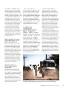
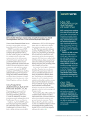
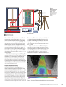
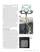
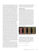
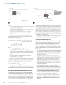
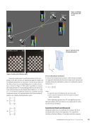
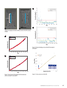
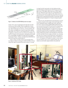
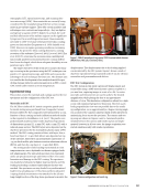
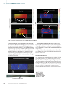
tomography (CT), optical microscopy, and scanning elec- tron microscopy (SEM). These materials are currently being considered for the manufacturing of the hot section compo- nents in gas turbine engines. They offer certain qualities and advantages over conventional super alloys—they are lighter and operate at a point of 200 °C higher. As a result, the cycle and fuel efficiencies of the turbine engines can be significant- ly improved. In an oxidizing environment, these materials are stable to 1600 °C because of the protective silica coating grown on their surface (Jorgensen et al. 1959 Smialek et al. 1999). However, in engine operating conditions containing moisture, the protective silica coating dissociates, causing recession of the substrate (Lee et al. 2001 Lee et al. 2005 Zhu et al. 2012). To overcome the recession issue, multilayered functionally graded environmental barrier coatings (EBCs) have been developed, which show adequate durability at tem- peratures up to 1450 °C. The target objectives of this work are to monitor the dam- age occurring in the specimen using the DIC technique com- pared to CT, optical microscopy, and SEM, and to assess the advantages of each technique for future use. The ultimate aim is to enable the development of an analytical model for pre- dicting damage initiation and propagation in an EBC-coated CMC tested under tension at room temperature. Experimental Setup This section covers the materials and coatings used in the test specimens and the configuration of the DIC test. Materials and EBC The SiC fiber-reinforced SiC matrix composite panels used for tensile testing were purchased from Composite Ceramic Products (GECCP). The composites were fabricated by a com- bination of slurry casting and melt infiltration method similar to that reported in Amirkhanov et al. (2017). The panels were predominantly machined into tensile dog-boned specimens of dimensions 152 mm (L), 13 mm (W), and 2.4 mm (T), with a reduced gauge section. The EBC layers were deposited on the dog-bone specimens by the atmospheric plasma spray (APS) method. The EBC coating consists of three sub layers: first, a bond coat layer of ~75 μm thick silicon was deposited on top of the substrate, followed by an intermediate mixed layer of ~75 μm thick mullite plus barium strontium aluminum silicate (BSAS), and then by a top layer of ~75 μm thick BSAS. The testing under tensile loading was initiated at room temperature in a servo-hydraulic test frame equipped with self-aligning grips. The unloaded specimen was examined under an optical microscope and observed by CT for crack formation and damage in the EBC coating. The specimen was loaded and reloaded at higher step load levels, and the loading/unloading continued until ultimate fracture was reached. The specimen was step loaded to a predetermined load level at a loading rate of 4 Kn/min and then unloaded. A spring-loaded extensometer was attached to the 25 mm long straight section of the dog-bone specimen to monitor the displacement. The displacement due to the loading applied was monitored by the DIC system. Figure 1 shows a stack of dog-bone specimens being examined under X-ray for obvious anomalies and premanufactured defects. DIC Test Configuration The DIC system in this study captures 2D displacement and strain fields using a 16MP monochrome camera coupled to a 300 mm lens, capturing images at a rate of 2.0 Hz. An exten- sion tube and teleconverter are used to achieve the desired magnification while placing the lens at an approximate distance of 1.5 m. This hardware configuration allows for a high zoom with minimized perspective distortion. However, a per- fectly perpendicular view was not possible due to the tensile rig configuration, so an approximately 3.5 degree viewing angle was accepted. The camera’s inherent depth of field allowed for maintaining focus across the specimen. The camera and test rig setup are shown in Figures 2 and 3. Automated synchro- nization between the camera and tensile rig was not imple- mented however, in all test cases, the image acquisition was started simultaneously with tensile rig initiation. Specimen stack Source Detector Figure 1. 200 KV microfocus X-ray source 2520 V cesium iodide detector (NASA Glenn, NDE Lab, Cleveland, Ohio). Test rig Digital image correlation camera Figure 2. Camera configuration and tensile rig. N O V E M B E R 2 0 2 2 • M AT E R I A L S E V A L U AT I O N 63
ASNT grants non-exclusive, non-transferable license of this material to  .
All rights reserved. © ASNT 2026. To report unauthorized use, contact: customersupport@asnt.org