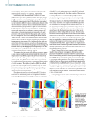
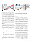
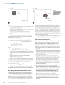
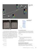
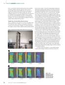
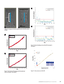
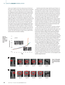
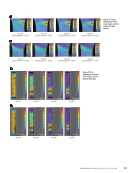
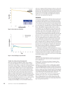
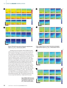
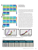
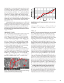
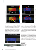
to achieve a stereo version for 3D-DIC measurement, which results in an increasing measurement uncertainty on the specimen area away from this camera because of the DOF influence. This limitation was confirmed by the analysis of displacement total RBMR from different camera combina- tions, as shown in Figure 6, where displacement total RBMR calculated from two-camera results contains larger values and an obvious inhomogeneity in distribution compared to the three-camera results. An out-of-plane motion away from the DIC system was applied in the sliding table measurement, and the mean displacement error values calculated from different camera combinations were compared, as shown in Figure 7b. Increas- ing measurement error up to 180 µm was observed for both the three-camera and two-camera results at a max out-of- plane displacement of 45 mm. The sliding table provides a unidirectional repeatability of 0.2 µm and a backlash of 2 µm, which may create a displacement error of 18 µm after nine displacement stages with an interval of 5 mm for an out-of- plane motion of 45 mm in the worst case. Still, this magnitude is negligible compared to the displacement error measured from the DIC system. Therefore, the main error source in this study may be caused by the influence of DOF in out-of-plane motion. During the out-of-plane motion, the sharpness of the speckle pattern on the specimen surface is reduced due to the deterioration of image focus, which leads to a reduced mea- surement accuracy. The far distance of acceptable sharpness to the focusing distance can be calculated as: (2) dfar = cF 2 _ f2 − cFd where c is the diameter of the circle of confusion, which can be considered as the camera pixel size of 3.45 µm in this work, F is the aperture number set as 5.6, d is the working distance equal to 850 mm, and f is the focal length of the lens, which is 23 mm. These parameters result in a far distance value of 27 mm in this work, which can be interestingly considered as a cut-off point between two different areas on the curves of the diagram in Figure 7b. For the curve area smaller than 27 mm in the diagram, a polynomial dependence between the mean displacement error and displacement stage of the sliding table was observed. For the curve area larger than 27 mm, a linear dependence was detected, which indicates an increasing influence of DOF on measurement error. Still, more systematic tests to study the influence of DOF on DIC measurement error need to be done in future work. Regardless of the increasing displacement error due to the DOF influence for both three-camera and two-camera results, the three-camera result still provides better performance compared to two-camera results based on displacement total RBMR values as shown in Figure 6 and Figure 7a. The smaller value and more homogeneous distribution of displacement total RBMR suggest a smaller measurement error inhomoge- neity in the measurement area within the FOVs of cameras, which leads to a more effective pixel usage. For example, only the central area of the specimen surface contains a displace- ment total RBMR value smaller than 10 µm in two-camera results as shown in Figure 6 meanwhile, the most specimen area evaluated from three-camera results show a measure- ment error below 10 µm. This is because the facet data points on the specimen surface can be viewed and evaluated from multiple combinations of camera pairs due to the addi- tional camera. Therefore, a smaller and evenly distributed 3D-residuum (i.e., measurement error) on the specimen surface can be achieved under the same influence of differ- ent error sources, such as distortion of the speckle pattern in facets due to titled camera viewing angles or an increasing influence of DOF in out-of-plane motion in this work. Conclusions A three-camera DIC system was introduced, and its per- formance was analyzed with three different experimental measurements. Images acquired from different camera com- binations were used for DIC evaluation to compare the test results between three-camera and two-camera results with the same evaluation parameters. The following advantages of the three-camera DIC system compared to conventional two-camera DIC system were determined in this work: Ñ A larger measurement area and improved surface coverage on test specimens with curved or uneven surface shapes can be achieved with one additional camera. Ñ The viewing angle of one camera can be set properly to a specimen surface as a reference camera for facet grid generation, which can not only minimize the misalignment and distortion of the facet grid due to the influence of a tilted camera viewing angle on image projection, but also maximize the number of facet data points on the specimen surface. Ñ Data points with the smallest 3D residuum evaluated from different combinations of camera pairs are employed in the evaluation result. Therefore, a smaller and more homoge- nous distributed measurement uncertainty can be deter- mined, especially in the overlapping area viewed by multiple cameras. Based on these advantages as well as considering the decreasing price of industrial cameras, a three-camera DIC system is not only optimal for conventional DIC applications, such as material testing with standard specimen sizes, but also shows great potential in various application areas, such as civil engineering or aerospace inspection, where the same measurement precision is required but for test specimens with larger sizes and irregular shapes. ME | DIGITALIMAGECORRELATION 40 M AT E R I A L S E V A L U AT I O N • N O V E M B E R 2 0 2 2

REFERENCES Chen, F., X. Chen, X. Xie, X. Feng, and L. Yang. 2013. “Full-field 3D measurement using multi-camera digital image correlation system.” Optics and Lasers in Engineering 51 (9): 1044–52. https://doi.org/10.1016/j. optlaseng.2013.03.001. Chen, X., L. Yang, N. Xu, X. Xie, B. Sia, and R. Xu. 2014. “Cluster approach based multi-camera digital image correlation: Methodology and its appli- cation in large area high temperature measurement.” Optics & Laser Tech- nology 57:318–26. https://doi.org/10.1016/j.optlastec.2013.08.005. Ke, X. D., H. W. Schreier, M. A. Sutton, and Y. Q. Wang. 2011. “Error assessment in stereo-based deformation measurements.” Experimental Mechanics 51 (4): 423–41. https://doi.org/10.1007/s11340-010-9450-3. Luo, P. F., Y. J. Chao, M. A. Sutton, and W. H. Peters, III. 1993. “Accurate measurement of three-dimensional deformations in deformable and rigid bodies using computer vision.” Experimental Mechanics 33 (2): 123–32. https://doi.org/10.1007/BF02322488. Malowany, K., M. Malesa, T. Kowaluk, and M. Kujawinska. 2017. “Multi- camera digital image correlation method with distributed fields of view.” Optics and Lasers in Engineering 98:198–204. https://doi.org/10.1016/j. optlaseng.2017.05.003. Niezrecki, C., P. Avitabile, C. Warren, P. Pingle, M. Helfrick, and E. P. Tomasini. 2010. “A review of digital image correlation applied to struc- tural dynamics.” AIP Conference Proceedings 1253 (1): 219–32. https://doi. org/10.1063/1.3455461. Orteu, J. J. 2009. “3-D computer vision in experimental mechanics.” Optics and Lasers in Engineering 47 (3-4): 282–91. https://doi.org/10.1016/j. optlaseng.2007.11.009. Orteu, J. J., F. Bugarin, J. Harvent, L. Robert, and V. Velay. 2011. “Multi- ple-camera instrumentation of a single point incremental forming process pilot for shape and 3D displacement measurements: Methodology and results.” Experimental Mechanics 51 (4): 625–39. https://doi.org/10.1007/ s11340-010-9436-1. Palanca, M., G. Tozzi, and L. Cristofolini. 2016. “The use of digital image correlation in the biomechanical area: A review.” International Biome- chanics 3 (1): 1–21. https://doi.org/10.1080/23335432.2015.1117395. Pan, B. 2018. “Digital image correlation for surface deformation measurement: Historical developments, recent advances and future goals.” Measurement Science & Technology 29 (8): 082001. https://doi. org/10.1088/1361-6501/aac55b. Peters, W. H., and W. F. Ranson. 1982. “Digital imaging techniques in experimental stress analysis.” Optical Engineering (Redondo Beach, Calif.) 21 (3): 427–31. https://doi.org/10.1117/12.7972925. Reu, P. 2013. “Stereo-rig design: Stereo-angle selection - part 4.” Experi- mental Techniques 37 (2): 1–2. https://doi.org/10.1111/ext.12006. Sutton, M. A., W. J. Wolters, W. H. Peters, W. F. Ranson, and S. R. McNeill. 1983. “Determination of displacements using an improved digital correla- tion method.” Image and Vision Computing 1 (3): 133–39. https://doi. org/10.1016/0262-8856(83)90064-1. Sutton, M. A., J. H. Yan, V. Tiwari, H. W. Schreier, and J. J. Orteu. 2008. “The effect of out-of-plane motion on 2D and 3D digital image correlation measurements.” Optics and Lasers in Engineering 46 (10): 746–57. https:// doi.org/10.1016/j.optlaseng.2008.05.005. Wang, Y., P. Lava, S. Coppieters, P. V. Houtte, and D. Debruyne. 2013. “Application of a multi‐camera stereo dic set‐up to assess strain fields in an erichsen test: Methodology and validation.” Strain 49 (2): 190–98. https:// doi.org/10.1111/str.12027. Zhang, Z. 2000. “A flexible new technique for camera calibration.” IEEE Transactions on Pattern Analysis and Machine Intelligence 22 (11): 1330–34. https://doi.org/10.1109/34.888718. N O V E M B E R 2 0 2 2 • M AT E R I A L S E V A L U AT I O N 41
ASNT grants non-exclusive, non-transferable license of this material to  .
All rights reserved. © ASNT 2026. To report unauthorized use, contact: customersupport@asnt.org