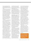
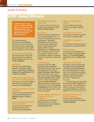
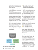
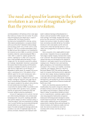
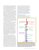
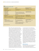
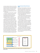
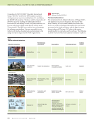
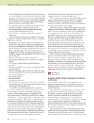
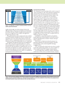
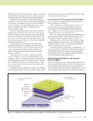
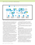
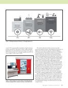
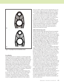
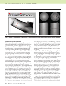
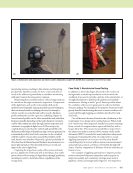
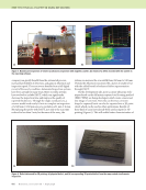
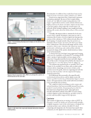
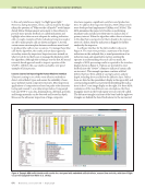
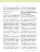
866 M A T E R I A L S E V A L U A T I O N • J U L Y 2 0 2 0 company can greatly benefit from the automated process, increased probability of detection, and gains in efficiency and inspection speed. The asset owner benefits from a full digital record of the asset’s condition. Automated inspection systems have been around for many years. More recently, systems have evolved to include PAUT, which can significantly decrease the inspection time and improve the quality of reported thicknesses. Through the single crystal process, a scanner would need nearly 10 min to complete an inspection of a 500 mm × 450 mm area at a resolution of 1 mm × 2 mm. By replacing the probe with PAUT, not only is the scan time reduced to less than 2 min, but because of the array, the system can increase the scan width from 450 mm to 510 mm. Overall, the efficiency is increased by a factor of nearly 6, but with the added benefit of enhanced defect representation through PAUT. On the development side, more accurate ultrasonic tech- niques based on the full matrix capture/total focusing method (FMC/TFM) are being developed, which create a more real- istic image of corrosion. Not only can the true corrosion shape be captured, but it can also be exported into a 3D point cloud, which can be used in other applications. Results of these kind of scans have already been used as input for 3D printing (Figure 6). This will enable better characterization of ME TECHNICAL PAPER w digital ndt solutions Figure 5. Nonintrusive inspection of vessel: (a) ultrasonic inspection with magnetic crawler (b) results of a defect recorded with the crawler in the reporting software. (a) (b) Figure 6. Defect data used for 3D printing: (a) physical defect and (b) corresponding 3D-printed defect from the map created via ultrasonic inspection. (a) (b)

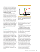
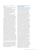
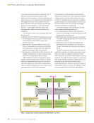
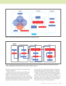
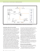
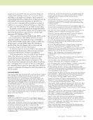
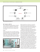
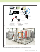
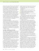
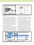
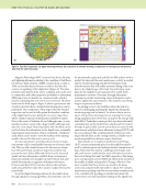
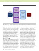
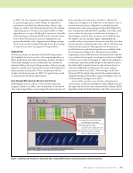
J U L Y 2 0 2 0 • M A T E R I A L S E V A L U A T I O N 867 discontinuities. In addition, these results have been used as input for fracture mechanics analysis (Adriano et al. 2019). Nozzles are an important class of joints used in pressure containing equipment. Because of their complex shape, nozzles are very difficult to inspect using ultrasonic tech- niques. Typical defects such as cracks and lack of fusion are highly sensitive to the beam orientation. Defects located close to the front surface often require the sound beams to be reflected off the backwall, making it very complicated when dealing with nozzles where the inside surfaces of the vessel are curved. Currently, the inspector has to estimate the local cross section of the complex 3D-shaped component in order to understand the location of received signals and interpret the position of the indications. CAD software already allows for the designing of complex nozzles thus, the operator can determine where to place its sensor, but there is no imme- diate combination of the ultrasound image and the actual geometry of the nozzle. Therefore, the inspection must be performed in a blind way and combined later with the geometrical design of the nozzle, which introduces delays and potential mistakes. A solution has been developed using augmented imaging, which uses the capabilities of simulated UT modeling and 3D CAD to produce understandable real-time images of the inspection. Using these models, the user can build a digital twin of the nozzle to be inspected and define the trajectory of the transducer to cover the region of interest (Figure 7). This solution was implemented on a portable PAUT unit (Figure 8). Its capability to read three-axis encoded nozzle scanners allows computing cross-section overlays as the operator moves the probe, which are superimposed with the ultrasonic data to produce real-time augmented imaging during the inspection. As all ultrasonic data are saved in the same file with synchronized probe positions and the digital nozzle, full analysis can then be achieved, as illustrated by Figure 9, which shows a 3D representation of the nozzle with detected indica- tions and related probe positions. The complete solution, including a nozzle scanner and selected transducer, has been successfully assessed by an inde- pendent research institute, who proposed a procedure for field inspection (Nageswaran 2016). This application matches well with the advent of the NDT 4.0 era by using combined digital models embedded in a portable system to provide understandable images to field operators. Conclusion The benefits of digitization are starting to show in NDT. In this paper, several case studies were presented with examples of digital integration. Each of the main features of Industry 4.0 is present in these cases: robotics, AI, AM, IoT, cloud computing, and integration into the inspection supply chain. Ultimately, it is the digital interconnection of these systems Figure 7. Screen display showing nozzle design and calculation of the probe trajectory. Figure 8. Nozzle inspection with a PAUT unit and specific scanners to hold the probe on the main pipe. Figure 9. A 3D view of the nozzle and detected indications related to probe position.
ASNT grants non-exclusive, non-transferable license of this material to  .
All rights reserved. © ASNT 2026. To report unauthorized use, contact: customersupport@asnt.org