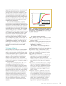
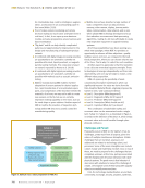
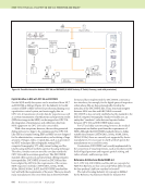
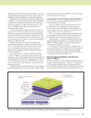
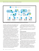
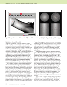
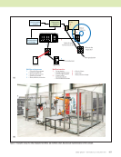
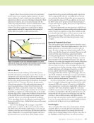
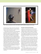
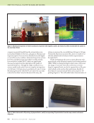
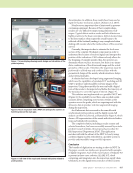
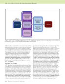
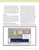
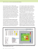
J U L Y 2 0 2 0 • M A T E R I A L S E V A L U A T I O N 817 NEW patents ROBERT E. SHANNON Associate Technical Editor US 10488371 Nondestructive inspection using thermoacoustic imagery system (A.M. Finn, A. Surana, M.O. Williams, E.A. Bernal, and O. Erdinc) This patent relates to a nondestructive thermoacoustic imagery system for prog- nostics and health management, preventa- tive maintenance, and repair of gas turbine engine parts. Manufactured components may incur defects or imperfections during manufacturing or suffer wear and incur defects during operation and thus are peri- odically inspected. Some defects are caused by delaminations or the improper bonding of composite structures, which may be detected by thermoacoustic tech- niques (also known as vibroacoustic, vibrothermography, thermosonic, or sonic infrared techniques) wherein vibration of the component induces localized heating at defect locations. The heating is detected by an infrared camera. Typically, the imagery is reviewed manually for the detection of defects. These reviews are tedious, time consuming, imprecise, and may be prone to errors. More recently, automated statistical analysis has been performed for crack detection using rapid exterior heating of a component and infrared imaging. For instance, pulsed ther- mography, in which a very short intense flash of light heats a component, has been used to show thermal conductivity of a coating. These techniques, however, require external heating of the component, which may not be applicable to composite material components. This technique uses an ultrasonic exci- tation source to induce elastic waves in the component such that each single frequency of excitation is converted into a broad band of frequencies that are partic- ular to resonant frequencies of the component. This vibrational energy is dissipated through conversion into heat due to friction or plastic deformation at defects in the component. A thermal signature is then observed with the ther- mography system. The amount of heat generated depends on the frequency and position of the excitation source and the size, shape, orientation, and depth of the dissipation site, as well as the excitation power level. Particular to this patent, a model of the component is stored in the component database to be registered to the thermal signature to provide structural information for location-dependent analysis. The model stored in the component database may be an as- designed model, an as-built model, a previous condition model, a model derived from the current thermal signature, and variations thereof for each component. In one example, the model may be a statis- tical distribution of pixel values from the thermal signature as constrained by the internal structure. Pixel values that fall outside of +/– 3s of the mean are consid- ered anomalous. If the anomalous pixels spatially cluster relative to the internal structure, a defect is determined to be present. The internal structure is registered to a thermal signature via the model of the component. The registration may make use of edges of the component and the model to scale, rotate, and/or translate the model to orient with respect to the component to elucidate the internal structure for automated reasoning about the location of potential defects. The automated reasoning may include geometry-specific algorithms for the detection of defects. The registration may include a random sample consensus (RANSAC) algorithm based on computed features where the features may include SIFT, SURF, ASIFT, other SIFT variants, Harris Corner features, SUSAN, FAST, a phase correlation, a normalized cross-correlation, GLOH, BRIEF, CenSure/STAR, ORB, and the like. The thermal signature is then compared with the model to initialize or constrain the detection of defects in the thermal signature to only the relevant predetermined area of the component, such as that defined by the internal structure. That is, the internal structure from the model is used to influence the detection of defects, particularly where the defect manifests as a “distorted pattern” in the thermographic image. This may be based on, for example, initialization of an active contour shape determination, a geometric restriction for predetermined areas over which statistical characteriza- tion is performed as priors in a Bayesian estimation, or another technique that limits portions of the thermographic image based on the model. In one example, a defect may be detected because it appears at a particular location with respect to the rigid internal structure, whereas an identical thermal signature defect that is not adjacent to the internal structure may be ignored. Other examples include the detection of defects by performing a geometry- dependent analysis, comparing the thermal signature to the model (which delineates the internal structure), a pixel segmentation of the thermal signature compared to the model, a statistical analysis of predetermined areas of the thermal signature, and the like. Or, detection may be performed by a deep learning classifier trained from available data, such as a library of user- characterized defect examples. Deep learning is the process of training or adjusting the weights of a deep neural network. In an embodiment, the deep neural network is a deep convolutional neural network. Deep convolutional neural
ASNT grants non-exclusive, non-transferable license of this material to  .
All rights reserved. © ASNT 2026. To report unauthorized use, contact: customersupport@asnt.org