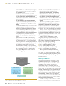
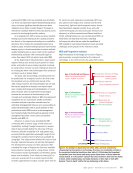
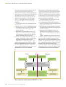
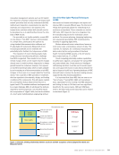
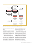
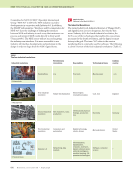
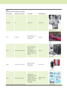
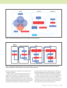
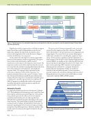
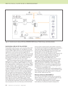
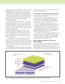
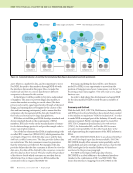
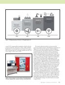
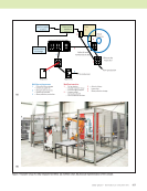
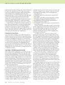
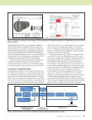
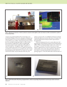
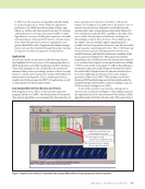
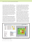
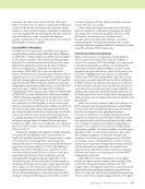
J U L Y 2 0 2 0 • M A T E R I A L S E V A L U A T I O N 841 allow the next generation of products to be optimized in a “feedforward” fashion. Figure 2 shows a closer look at serial production and inspection in the supply chain. It begins with material suppliers, who already carry out inspections on the raw material, continues through inspections at the component suppliers, and ends at the inspections conducted at the OEMs who assemble the final product and the in-service inspections during the use of the products. All of these inspections provide results that could be integrated into an Industry 4.0 world through appropriate interfaces and thus, as described previously, contribute to improving production and design. Figure 3 shows the interfaces of each individual inspection step. The input interfaces marked in green (1) supply the order data (2) provide the inspector with information on the component (3) serve to correctly set the devices, the inspec- tion, the mechanics, and the evaluation and (4) document the results in accordance with the specifications. Inspection Production Inspection Production Machining Inspection Receiving and acceptance inspections Machining Assembly Service inspection Commissioning and acceptance inspections Operation End of life Material suppliers Component suppliers OEM User Figure 2. Typical supply chain with inspection steps in serial production. There could potentially be additional steps between component suppliers and OEM, like machining shops. (© Vrana GmbH, used with permission). Design NDE Design Standards NDE specifications Material science Manufacturing Field test inspections and additional inspections Optimization NDE Optimization design Production prototype(s) Inspection Production Commissioning Design Field Test Production Feedback Figure 1. Typical product development process (© Vrana GmbH, used with permission).

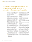
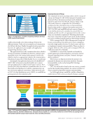
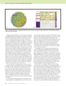
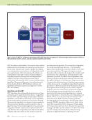
842 M A T E R I A L S E V A L U A T I O N • J U L Y 2 0 2 0 Digitalization of these input interfaces will help to support inspectors in their work by helping them avoid errors in inspection, optimize the inspection, and ensure a clear, revision-safe assignment of the results by means of digital machine identification of a component. On the output side, the inspection system’s status infor- mation and the inspection results are generated. The inspec- tion system’s status information could be used for maintenance and to improve the inspection system itself. The inspection results consist of the actual test data, the raw and processed data, the metadata (meaning the framework param- eters of the inspection and evaluation), and, finally, the reported values. The reported values represent the key performance indicators (KPIs) of the inspection. For industry, interpreted data are the easiest to evaluate. There- fore, the reported values are usually the most relevant data obtained from the inspection. Consideration should be given to whether the currently reported values are sufficient for NDE 4.0 purposes or whether the results to be reported should be extended for statistical purposes and thus for greater benefit to the customer. Automation Pyramid In a digitized industrial production environment (“Industry 3.0”), the techniques and systems in process control are classi- fied using the automation pyramid (Figure 4). The automa- tion pyramid represents the different levels in industrial production. Each level has its own task in production, whereby there are fluid boundaries depending on the opera- tional situation. This model helps to identify the potential systems/levels for Industry 4.0 and NDE 4.0 interaction (in particular regarding the beforementioned input and output parameters of an NDE inspection). However, validity of this model needs to be discussed in regard to Industry 4.0 and NDE 4.0. The process level (bottom of pyramid) is the sensor and actuator level for simple and fast data collection. The field level is the interface to the production process using input and output signals. The control level uses systems like program- mable logic controllers for controlling the equipment. Super- visory control and data acquisition of all the equipment in a shop happens at the shop floor level. Manufacturing execution systems (MESs) are usually used for collecting all production data and production planning at the plant level. Finally, enter- prise resource planning (ERP) systems control operation planning and procurement for a company. Systems for product lifecycle management (PLM) are usually not included in the automation pyramid (as the automation pyramid visualizes the automation during production and not during the lifecycle of a product), but such PLMs are clearly connected to both the MES and ERP systems. ME TECHNICAL PAPER w nde 4.0: perception and reality Existing documentation Inspection system status information Reports with indications, sensitivities, OK/not OK, and deviations Inspection Data processing Raw data Processed data Equipment, inspection, mechanical, and processing settings Metadata Interpretation Documentation of results Component information Inspection equipment Environmental parameters Inspector certification Procedures and specifications Figure 3. Typical sequence of an automated inspection in serial production (can also in principle be used for manual testing) (© Vrana GmbH, used with permission). Process level Production PLC SCADA MES ERP Input/output signals Field level Programmable logic controller: control level Supervisory control and data acquisition: shop floor level Manufacturing execution system: plant level Enterprise resource planning: enterprise level Figure 4. The automation pyramid (© Vrana GmbH, used with permission).
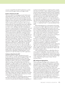
ASNT grants non-exclusive, non-transferable license of this material to  .
All rights reserved. © ASNT 2026. To report unauthorized use, contact: customersupport@asnt.org