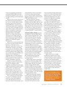
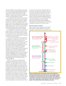
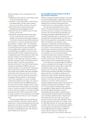
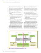
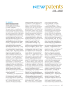
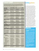
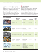
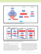
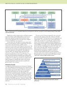
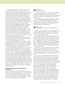
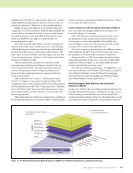
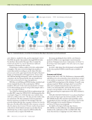
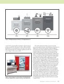
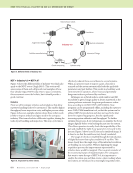
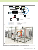
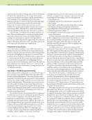
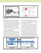
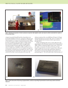
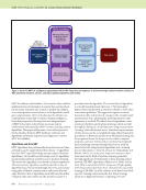
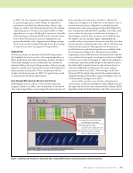
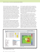
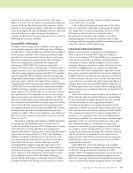
J U L Y 2 0 2 0 • M A T E R I A L S E V A L U A T I O N 863 running outside the boundaries set at instrument validation, in order to share instrument configuration, historical data, and reports. For the owner/operator, it could mean receiving real- time feedback of testing results, monitoring inspection progres- sion, and consulting realistic 3D tube sheets and bundle maps, which enable spotting of patterns in the occurrence of defects and helps determine the underlying problems to degradation. This could definitively help to smooth turn-around planning. The processing of data using cloud processing has been achieved and trialed as well, but issues concerning data ownership and data security have, so far, limited the applica- tion of cloud storage and processing as a commercial model. Case Study 2: Storage Tank Testing Storage tanks may operate for many years without interrup- tion. Maintenance windows are small, and, depending on the stored product, the tank may be emptied for inspection and repair only once every 20 years. The inspection of a storage tank tends to use a range of technologies for its components such as the floor, wall, roof, and ancillaries. This may involve one service provider, or several, and results may be delivered directly to the owner, or to an intermediary such as a mainte- nance contractor. As supply relationships are very diverse, there is an obligation to use open data formats if digital inte- gration is to be achieved. One of the most common is simple comma-separated values (CSV) files. With large amounts of data available, oil companies have started to harness the idea of digital twins in order to gain a better holistic insight into the behavior and life expectancy of their equipment. This can begin by first creating a virtual representation of the structure in computer-aided design (CAD) software. Data gathered from recent inspections can then be used to adjust the digital twin to create a current-case model of the asset. This could be done by deforming the 3D model itself or with a color-coded textured overlay of recorded maps from corrosion-mapping tools. This would result in a benchmark representation of the asset. Further information, such as historic inspections and previous repairs, could be added to the digital twin to complete its virtual representation. This baseline model is considered the “initial- ization” stage of the digital twin and is represented by the first stage in the life of a digital twin, as illustrated in Figure 2. Digital twin baseline Physical asset Key frame audit ● Perform inspection Digital twin ● 3D point cloud ● CAD drawing Inspection ● Assess the present condition Historical data ● Archived inspection reports ● Historic inspection data Update digital twin ● Establish new baseline Schedule maintenance Monitoring Update digital twin Decommission asset Fit for purpose? Yes No Out of service In service (1–20 year period) Digital twin creation (initialization) Figure 2. Simple illustration of the creation of a digital twin and its upkeep throughout the life of an asset. Feature tags Legend with feature tags Scan results of tube Complex plane eddy current signals Figure 1. Nondestructive testing of a heat exchanger: (a) 3D representation after testing showing defects and flawed tubes (b) results of feature detection software. (a) (b)

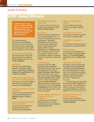
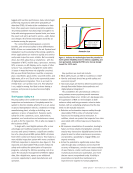
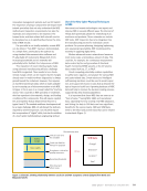
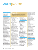
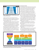
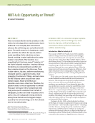
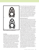
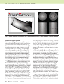
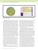
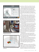
864 M A T E R I A L S E V A L U A T I O N • J U L Y 2 0 2 0 Magnetic flux leakage (MFL) scanners have been collecting and digitizing information relating to the condition of tank floors for 20 years. Early adopters of MFL scanners from as early as 1999 can use their data as historic records to feed into the creation (or updating) of the digital twin (Figure 3). This data provides some history of the asset’s condition and can be used in conjunction with other inspection modalities or subsequent MFL inspections to identify any common trends, which is ideal for scheduling the next out-of-service interval. This then feeds into the third stage in Figure 2, which represents an out- of-service interval where a detailed internal inspection can be performed. One component of this stage is that the detailed inspection can be used to fully update the baseline condition of the digital twin because during the in-service stage, there will be a limited amount of information available to update. Data is the center of Industry 4.0, and although semi- or auto- mated procedures can provide a huge benefit with large-scale data sets, even simple visual inspections with checklists can be used to bolster the information to the digital twin, continually improving its representation. This is considered a “keyframe” audit, which can be used to reset the baseline of the existing model to be used for the next in-service cycle. It is also important to note that advancements in inspec- tion systems can be considerable between out-of-service inter- vals. This can add complications as the data may no longer have the same format, and newer inspection systems may present the same defect differently. However, the increased quality and new information available from contemporary inspection systems (for example, top-side/bottom-side auto- mated discontinuity recognition with improved sensors [Pearson and Boat 2012]) can also enhance the keyframe audit and add further value when used to readjust the baseline periodically. In current digital twinning software for the tank bottom, through signal processing algorithms, discontinuities can now be automatically segmented and fed into RBI analysis tools to predict the time until the next maintenance activity is needed and the overall remaining tank life. Development work includes features that will enable automatic fitting of the scan data on the digital image of the tank. From this data, repair plans for the tank floor can be generated to enable faster maintenance activities. Over time, through subsequent scanning or periodic monitoring, sensor information can be used to update the representation of the tank floor and bring it up to its present condition. As gaining access to the tank floor when the tank is in service is challenging, updating the digital twin during the monitoring stage can be limited. To advance the in-service aspect of inspection, developments are ongoing for incorpo- rating equipment into robots that can inspect the storage tank while filled. Tanks that contain product may have substantial contaminations on the tank bottom, which need to be tested through. A pulsed eddy current system has been tested in this environment and phased array ultrasonic testing (PAUT) will be soon evaluated. The complementarity of these two tech- niques should allow, in the coming months, a reliable way of monitoring tank floors between major shutdowns. Alternatively (or in tandem), fixed Internet of Things (IoT) sensors permanently placed on the tank floor may be used to perform remote and perhaps wireless transmissions of data. At present, this remains a challenge, but if made avail- able, such sensors could monitor areas of localized corrosion discovered during the tank’s last MFL inspection. This brings us to one important note for NDT 4.0, which is the security of the readily available and popular IoT range of devices. One must consider that these devices are aimed to be always connected and potentially vulnerable to attack. For example, smart sensor spoofing could be one area where security needs to be considered. In spoofing, an attacker may mimic the smart sensor and send fraudulent readings to the digital twin ME TECHNICAL PAPER w digital ndt solutions Figure 3. Tank floor inspection: (a) digital twinning software (b) screenshot of software showing a comparison of new (top) and old (bottom) data from the same floor plate. (a) (b)
ASNT grants non-exclusive, non-transferable license of this material to  .
All rights reserved. © ASNT 2026. To report unauthorized use, contact: customersupport@asnt.org