NDT FOR ELECTRIFIED VEHICLES: BEYOND
BATTERY CELL INSPECTION
BY MEGAN MCGOVERN, ERIK HUEMILLER, DMITRIY BRUDER,
SEAN WAGNER, ROBIN JAMES, AND RASHMI PRASAD
While battery cells dominate the conversation around nondestructive
testing (NDT) for electric vehicles, focusing too narrowly on them
risks overlooking other critical components. Electric motors, power
electronics, battery modules, and related systems also demand rigorous
inspection to ensure vehicle safety and performance. Recognizing
these often-overlooked NDT applications reveals their essential role in
supporting the future of electrified mobility.
Introduction
Publications on nondestructive testing
(NDT) of electric vehicle (EV) compo-
nents are, understandably, heavily dom-
inated by battery cell inspection applica-
tions [1–4]. This dominance is justified,
since battery cells are the single most
crucial and distinguishing feature of
vehicle electrification—e.g., EVs, hybrids,
plug-in hybrids, and extended-range
electric vehicles (EREVs). Cells must
operate as intended to ensure maximum
range, safety, and performance.
However, the heavy emphasis on battery
cells in the literature may lead those
unfamiliar with EVs to overlook NDT for
other essential components. Although
automotive engineers recognize the
importance of non-cell components,
the authors’ purpose here is to famil-
iarize the reader with NDT inspection
for several of the non-cell components
required for electrified vehicle opera-
tion. While these discussion points apply
to all electrified vehicles (e.g., hybrids,
plug-in hybrids, EREVs), only “EVs” will
be referred to throughout this article for
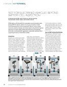
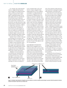
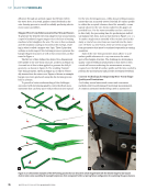
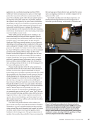
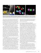
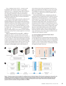
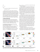
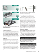
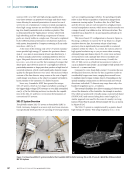
simplicity. Figure 1 presents a simpli-
fied schematic of these various vehicle
architectures.
Non-Cell NDT for Electrified Vehicles
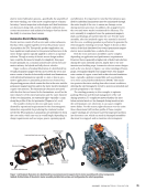
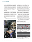
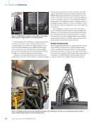
The importance of NDT in EV design
cannot be overstated. NDT is crucial
for ensuring safety and performance,
serving as a safeguard against issues
such as desoldering or delamination
of parts that can lead to catastrophic
failures. It also verifies that the vehicle
and its components comply with spec-
ifications. NDT for EVs is used at every
stage of the vehicle’s life: at the com-
ponent manufacturing level, during
vehicle assembly, throughout in-service
operation, and even to support root-
cause investigations through post-failure
FEATURE
|
NDTTUTORIAL
Hybrid electric vehicle &
plug-in hybrid electric vehicle
*Only parallel configuration shown
Extended-range electric vehicleBattery electric vehicleInternal combustion engine
ICE BEV HEV EREV
PHEV
Figure 1. Simplified schematic showing high-level differences between architectures: (a) internal combustion engine (ICE) (b) battery electric
vehicle (BEV) (c) hybrid and plug-in electric vehicle (HEV/PHEV) (d) extended-range electric vehicle (EREV). Note: These schematics are for
illustration purposes only and are not meant to accurately depict vehicle architectures. (Images of components, including the battery and electric
motor, appear from [5–7] with permission.)
26
M AT E R I A L S E V A L U AT I O N • J A N U A R Y 2 0 2 6
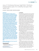
BATTERY CELL INSPECTION
BY MEGAN MCGOVERN, ERIK HUEMILLER, DMITRIY BRUDER,
SEAN WAGNER, ROBIN JAMES, AND RASHMI PRASAD
While battery cells dominate the conversation around nondestructive
testing (NDT) for electric vehicles, focusing too narrowly on them
risks overlooking other critical components. Electric motors, power
electronics, battery modules, and related systems also demand rigorous
inspection to ensure vehicle safety and performance. Recognizing
these often-overlooked NDT applications reveals their essential role in
supporting the future of electrified mobility.
Introduction
Publications on nondestructive testing
(NDT) of electric vehicle (EV) compo-
nents are, understandably, heavily dom-
inated by battery cell inspection applica-
tions [1–4]. This dominance is justified,
since battery cells are the single most
crucial and distinguishing feature of
vehicle electrification—e.g., EVs, hybrids,
plug-in hybrids, and extended-range
electric vehicles (EREVs). Cells must
operate as intended to ensure maximum
range, safety, and performance.
However, the heavy emphasis on battery
cells in the literature may lead those
unfamiliar with EVs to overlook NDT for
other essential components. Although
automotive engineers recognize the
importance of non-cell components,
the authors’ purpose here is to famil-
iarize the reader with NDT inspection
for several of the non-cell components
required for electrified vehicle opera-
tion. While these discussion points apply
to all electrified vehicles (e.g., hybrids,
plug-in hybrids, EREVs), only “EVs” will
be referred to throughout this article for
simplicity. Figure 1 presents a simpli-
fied schematic of these various vehicle
architectures.
Non-Cell NDT for Electrified Vehicles
The importance of NDT in EV design
cannot be overstated. NDT is crucial
for ensuring safety and performance,
serving as a safeguard against issues
such as desoldering or delamination
of parts that can lead to catastrophic
failures. It also verifies that the vehicle
and its components comply with spec-
ifications. NDT for EVs is used at every
stage of the vehicle’s life: at the com-
ponent manufacturing level, during
vehicle assembly, throughout in-service
operation, and even to support root-
cause investigations through post-failure
FEATURE
|
NDTTUTORIAL
Hybrid electric vehicle &
plug-in hybrid electric vehicle
*Only parallel configuration shown
Extended-range electric vehicleBattery electric vehicleInternal combustion engine
ICE BEV HEV EREV
PHEV
Figure 1. Simplified schematic showing high-level differences between architectures: (a) internal combustion engine (ICE) (b) battery electric
vehicle (BEV) (c) hybrid and plug-in electric vehicle (HEV/PHEV) (d) extended-range electric vehicle (EREV). Note: These schematics are for
illustration purposes only and are not meant to accurately depict vehicle architectures. (Images of components, including the battery and electric
motor, appear from [5–7] with permission.)
26
M AT E R I A L S E V A L U AT I O N • J A N U A R Y 2 0 2 6