For example, when inspecting laser
welds on a highly reflective material
such as copper, laser welding increases
surface roughness in localized areas,
raising the emissivity of the welded
region. A multi-flash strategy [13] can
help mitigate reflections, provided suf-
ficient thermal energy is absorbed,
reaches the inspection depth of interest,
and is emitted. This is therefore only
practical for very thin welds with a rough
textured surface. An alternative approach
for inspecting the subsurface condition
of a weld is laser ultrasound [14–16].
Laser ultrasound is a powerful tool
however, the cycle times required are
often not suitable for a manufacturing
environment. Furthermore, achieving
an adequate signal-to-noise ratio may
require operating in the ablation regime,
which can result in marking the part.
Machine vision is another commonly
used technique for noncontact weld
inspection. While it is an effective, rapid
inspection tool, its limitations include
its inability to assess subsurface condi-
tions. Even so, many inferences about
joint quality can be drawn from surface
features [17], and machine vision can serve
as a powerful tool for weld inspection in
components such as laser welds found in
battery trays or electric motor stators.
Although 100% in-line inspection
is the ultimate goal, operational envi-
ronment constraints can render this
impossible. For this reason, audits
with offline nondestructive tools or
destructive testing still have their place.
Offline nondestructive tools (i.e., those
requiring cycle times not suitable for
in-line manufacturing) can be used,
with two common examples being
manual inspection or X-ray computed
tomography (CT). Manual inspection
may involve a straightforward visual
assessment by a trained operator or a
hands-on “screening” technique collo-
quially referred to as a “pick test,” where
an operator attempts to pry apart a weld.
The latter is, of course, destructive if the
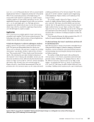
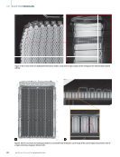
weld is weak. X-ray direct radiography
(2D) or CT (3D) is used for inspecting
various assemblies such as battery dis-
connect units (BDUs) or power electron-
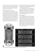
ics like inverters. X-ray can also be used
to inspect adhesive joints, such as struc-
tural adhesive in battery modules, to
determine whether they have achieved
wet-out (where “wet-out” refers to the
condition in which the adhesive achieves
complete contact with and uniformly
covers the surface to which it is applied.
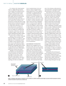
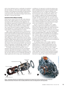
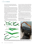
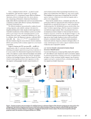
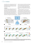
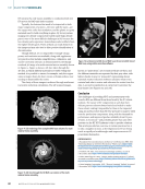
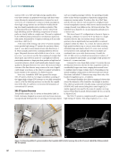
See Figure 3). The effectiveness of X-ray
for this purpose depends on the module
geometry, location of the adhesive, and
wet-out requirements.
NON-PERMANENT CONNECTIONS
While the above examples focus on
permanent joints, there are also several
non-permanent joints in the vehicle that
require careful consideration during
inspections, such as bolted electrical
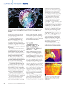
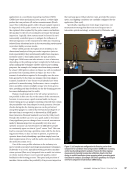
joints. Passive infrared thermography is
an effective method for inspecting bolted
joints in battery packs [18]. By energiz-
ing the pack electrically and using a
thermal camera, inspectors can identify
“hot spots” that indicate areas of high
resistance, often associated with faulty
joints. This technique enables detection
of potential issues, ensuring the integrity
and performance of the battery pack.
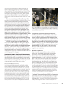
Bolted joints between the pack and
the motor inverter connect components
that span the vehicle and are designed
to allow for servicing and component
replacement. When considering the
joint’s electrical resistance, special con-
sideration must be given to the contact
surfaces of the busbar and the mating
cable lead. Both surfaces must be flat
and free of debris to ensure proper
contact. Additionally, the fastener torque
must be accurate. Traditional techniques
such as fastener torque monitoring
[19] can be conveniently applied since
fasteners must be torqued to specifica-
tion. This approach, however, does not
guarantee optimal mating contact at the
joint. Debris between surfaces or defor-
mation of one or more surfaces can still
lead to poor electrical performance. One
potential area for research is the appli-
cation of less-common production NDT
techniques such as laser ultrasonics [14],
where a change in fastener strain after
torquing can potentially be detected
through changes in travel time of the
acoustic signal. Moreover, as a noncon-
tact technique, it could prove suitable for
monitoring fastener torque during live
pack operation.
Ensuring the electrical integrity of
power and signal connectors in vehicles
is essential for reliable performance.
Apart from the common methods using
external sensors, signal conditioners,
and data acquisition hardware for non-
invasive testing, allowing for thorough
NDT TUTORIAL
|
ELECTRICVEHICLES
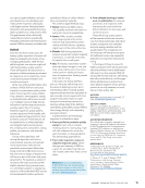
External structure
(transparent for
representation purposes)
Polymeric interface material
External structure
Unwetted region (e.g., void or delamination)
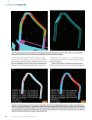
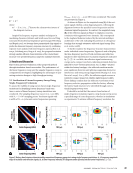
Figure 3. Schematic representation of imperfect wet-out conditions in which a localized unwetted region is present within the polymeric interface
material: (a) isometric view (b) cross-sectional view.
28
M AT E R I A L S E V A L U AT I O N • J A N U A R Y 2 0 2 6
welds on a highly reflective material
such as copper, laser welding increases
surface roughness in localized areas,
raising the emissivity of the welded
region. A multi-flash strategy [13] can
help mitigate reflections, provided suf-
ficient thermal energy is absorbed,
reaches the inspection depth of interest,
and is emitted. This is therefore only
practical for very thin welds with a rough
textured surface. An alternative approach
for inspecting the subsurface condition
of a weld is laser ultrasound [14–16].
Laser ultrasound is a powerful tool
however, the cycle times required are
often not suitable for a manufacturing
environment. Furthermore, achieving
an adequate signal-to-noise ratio may
require operating in the ablation regime,
which can result in marking the part.
Machine vision is another commonly
used technique for noncontact weld
inspection. While it is an effective, rapid
inspection tool, its limitations include
its inability to assess subsurface condi-
tions. Even so, many inferences about
joint quality can be drawn from surface
features [17], and machine vision can serve
as a powerful tool for weld inspection in
components such as laser welds found in
battery trays or electric motor stators.
Although 100% in-line inspection
is the ultimate goal, operational envi-
ronment constraints can render this
impossible. For this reason, audits
with offline nondestructive tools or
destructive testing still have their place.
Offline nondestructive tools (i.e., those
requiring cycle times not suitable for
in-line manufacturing) can be used,
with two common examples being
manual inspection or X-ray computed
tomography (CT). Manual inspection
may involve a straightforward visual
assessment by a trained operator or a
hands-on “screening” technique collo-
quially referred to as a “pick test,” where
an operator attempts to pry apart a weld.
The latter is, of course, destructive if the
weld is weak. X-ray direct radiography
(2D) or CT (3D) is used for inspecting
various assemblies such as battery dis-
connect units (BDUs) or power electron-
ics like inverters. X-ray can also be used
to inspect adhesive joints, such as struc-
tural adhesive in battery modules, to
determine whether they have achieved
wet-out (where “wet-out” refers to the
condition in which the adhesive achieves
complete contact with and uniformly
covers the surface to which it is applied.
See Figure 3). The effectiveness of X-ray
for this purpose depends on the module
geometry, location of the adhesive, and
wet-out requirements.
NON-PERMANENT CONNECTIONS
While the above examples focus on
permanent joints, there are also several
non-permanent joints in the vehicle that
require careful consideration during
inspections, such as bolted electrical
joints. Passive infrared thermography is
an effective method for inspecting bolted
joints in battery packs [18]. By energiz-
ing the pack electrically and using a
thermal camera, inspectors can identify
“hot spots” that indicate areas of high
resistance, often associated with faulty
joints. This technique enables detection
of potential issues, ensuring the integrity
and performance of the battery pack.
Bolted joints between the pack and
the motor inverter connect components
that span the vehicle and are designed
to allow for servicing and component
replacement. When considering the
joint’s electrical resistance, special con-
sideration must be given to the contact
surfaces of the busbar and the mating
cable lead. Both surfaces must be flat
and free of debris to ensure proper
contact. Additionally, the fastener torque
must be accurate. Traditional techniques
such as fastener torque monitoring
[19] can be conveniently applied since
fasteners must be torqued to specifica-
tion. This approach, however, does not
guarantee optimal mating contact at the
joint. Debris between surfaces or defor-
mation of one or more surfaces can still
lead to poor electrical performance. One
potential area for research is the appli-
cation of less-common production NDT
techniques such as laser ultrasonics [14],
where a change in fastener strain after
torquing can potentially be detected
through changes in travel time of the
acoustic signal. Moreover, as a noncon-
tact technique, it could prove suitable for
monitoring fastener torque during live
pack operation.
Ensuring the electrical integrity of
power and signal connectors in vehicles
is essential for reliable performance.
Apart from the common methods using
external sensors, signal conditioners,
and data acquisition hardware for non-
invasive testing, allowing for thorough
NDT TUTORIAL
|
ELECTRICVEHICLES
External structure
(transparent for
representation purposes)
Polymeric interface material
External structure
Unwetted region (e.g., void or delamination)
Figure 3. Schematic representation of imperfect wet-out conditions in which a localized unwetted region is present within the polymeric interface
material: (a) isometric view (b) cross-sectional view.
28
M AT E R I A L S E V A L U AT I O N • J A N U A R Y 2 0 2 6