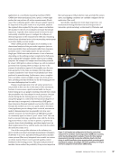
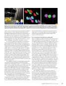
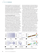
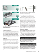
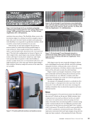
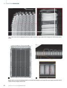
Nayar (1996) and Baleani et al. (2021). The wire-form is typi-
cally held in a fixed position using either a robot end-effector
or a test station, placing the wire-form within the path of the
telecentric optics. Images of the wire-form’s 2D silhouette are
then captured. To properly assess the critical 3D features of a
given wire-form shape, typically two to three perspective views
are necessary. Analysis is performed on the silhouette images
from the different perspectives to ensure the form is within the
accepted tolerance criteria.
However, getting reliable image data from the different per-
spective views repeatably requires a high degree of positional
control and accurate alignment of the wire-form within the
optical field of view to avoid erroneous measurements. Time
improvements are possible if alignment and positioning are
automated, but each articulation position comes at the cost of
time required to make a full assessment. Having a methodol-
ogy that requires minimal part manipulation, uses hardware
capable of fast data acquisition and analysis, and provides all
the necessary perspectives to map the wire-form shape fully is,
therefore, critical to achieving 100% in-process part inspection.
Methodology for Rapid High-Fidelity 3D Wire-Form
Reconstruction
This section describes the sensor technology (laser-projected
structured light sensors), their technical capabilities, and key
considerations in data collection. Common application use
cases of these sensors will also be discussed. A critical aspect
of this study involves the simultaneous operation of multiple
sensors and the ability to fuse their data outputs. Discussion
regarding this topic is also included in this section.
Structured Light Sensors
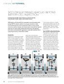
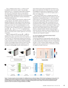
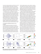
Structured light imaging operates on principles similar to stereo
vision techniques. In stereo vision, a triangulation relationship
is formed between two camera sensors and the object being
imaged. In structured light imaging, a single camera sensor is
used in conjunction with a pattern-projection light source to
form a triangulation relationship with the object to be inspected.
The projected pattern illuminates the object while the camera
sensor captures an image of the pattern as deformed by the
object surface. If the camera sensor and the pattern projec-
tion light source have been calibrated, it is then possible to
reconstruct the 3D object surface by analyzing correspond-
ing features between the projected pattern and the pattern
observed in the captured image. Several factors impact the
overall dimensional accuracy of a 3D structured light sensor,
including how the pattern is controlled and projected onto the
object surface through modulation, the selected optics, and the
light source. For more in-depth discussion regarding the coding
and decoding of projected structured light patterns, how these
patterns are controlled through modulation systems, and the
pros and cons of strategies for 3D reconstruction, please refer to
Yang and Gu (2024) and Bell et al. (2016).
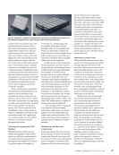
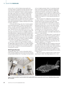
Within industry, laser-based structured light projec-
tion sensors are used for a variety of applications. The most
prominent is identifying parts and their orientation in 3D space
for bin-picking robotic systems (Kratky 2019). This arrangement
typically has a stationary structured light sensor that scans the
bin and reports the position and orientation of parts for a robot
system to automatically collect them for production. Other
uses relate to applications that require tracking changes in
part geometry over time, such as providing adaptive feedback
in additive manufacturing processes (Garmendia et al. 2018).
Having a stationary sensor also makes it possible to track
surface changes due to evolving environmental conditions
(Zaidan et al. 2024) or to track dunnage on conveyors within
warehouses.
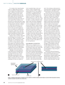
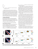
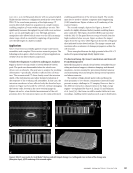
There are, however, application-specific considerations
that must be investigated thoroughly to ensure these sensors
operate as needed. Object surface finish and its response to the
wavelength of light from the structured light sensor can con-
siderably impact the ability to properly receive the deformed
projection pattern from the surface. This can have a dramatic
impact on the decoding analysis process for 3D reconstruc-
tion and may result in missing point cloud data. The overall
surface geometry of the object being investigated also needs to
be taken into consideration with regards to the experimental
setup. If the geometry prevents the light pattern from reflect-
ing back to the camera sensor, holes or gaps will appear in the
data (Gupta et al. 2011), which can only be filled by articulating
either the sensor or the object relative to each other (Park and
Kak 2008). This is commonly performed within industry when
reconstructing challenging components (Antolin-Urbaneja et
al. 2024). The drawback is that having more points of articula-
tion increases the time required to produce a final 3D render-
ing and necessitates more sophisticated point cloud analysis
algorithms to fuse data from different perspectives without
introducing additional error sources.
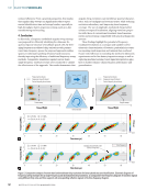
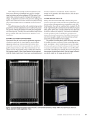
Common World Coordinate System (WCS) Calibration
If only a single structured light sensor unit is used, calibra-
tion is typically carried out using a 2D calibration target. The
target is placed at various positions and orientations relative
to the sensor—while remaining within its field of view—
and data is acquired. This process allows the camera and
pattern-projection light source to be calibrated relative to
each other and establishes an internal coordinate system for
the sensor. When more than one sensor is used, this method
can still be applied to provide a common WCS, provided all
sensors are fixed and have clear view of the 2D calibration
target as it is positioned within the setup array’s effective field
of view (Kaiser et al. 2024). However, this approach generally
works only when all sensors are oriented roughly in the same
direction relative to the part being inspected.
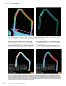
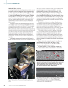
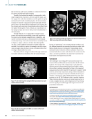
Due to the complex 3D surface of the wire-forms, fully
reconstructing a point cloud representation of the wire-form
apex requires multiple structured light sensor perspectives.
This can be accomplished through articulation, though at
the cost of inspection time and the need for advanced point-
cloud meshing strategies. However, in the interest of meeting
ME
|
ELECTRICVEHICLES
38
M AT E R I A L S E V A L U AT I O N • J A N U A R Y 2 0 2 6
cally held in a fixed position using either a robot end-effector
or a test station, placing the wire-form within the path of the
telecentric optics. Images of the wire-form’s 2D silhouette are
then captured. To properly assess the critical 3D features of a
given wire-form shape, typically two to three perspective views
are necessary. Analysis is performed on the silhouette images
from the different perspectives to ensure the form is within the
accepted tolerance criteria.
However, getting reliable image data from the different per-
spective views repeatably requires a high degree of positional
control and accurate alignment of the wire-form within the
optical field of view to avoid erroneous measurements. Time
improvements are possible if alignment and positioning are
automated, but each articulation position comes at the cost of
time required to make a full assessment. Having a methodol-
ogy that requires minimal part manipulation, uses hardware
capable of fast data acquisition and analysis, and provides all
the necessary perspectives to map the wire-form shape fully is,
therefore, critical to achieving 100% in-process part inspection.
Methodology for Rapid High-Fidelity 3D Wire-Form
Reconstruction
This section describes the sensor technology (laser-projected
structured light sensors), their technical capabilities, and key
considerations in data collection. Common application use
cases of these sensors will also be discussed. A critical aspect
of this study involves the simultaneous operation of multiple
sensors and the ability to fuse their data outputs. Discussion
regarding this topic is also included in this section.
Structured Light Sensors
Structured light imaging operates on principles similar to stereo
vision techniques. In stereo vision, a triangulation relationship
is formed between two camera sensors and the object being
imaged. In structured light imaging, a single camera sensor is
used in conjunction with a pattern-projection light source to
form a triangulation relationship with the object to be inspected.
The projected pattern illuminates the object while the camera
sensor captures an image of the pattern as deformed by the
object surface. If the camera sensor and the pattern projec-
tion light source have been calibrated, it is then possible to
reconstruct the 3D object surface by analyzing correspond-
ing features between the projected pattern and the pattern
observed in the captured image. Several factors impact the
overall dimensional accuracy of a 3D structured light sensor,
including how the pattern is controlled and projected onto the
object surface through modulation, the selected optics, and the
light source. For more in-depth discussion regarding the coding
and decoding of projected structured light patterns, how these
patterns are controlled through modulation systems, and the
pros and cons of strategies for 3D reconstruction, please refer to
Yang and Gu (2024) and Bell et al. (2016).
Within industry, laser-based structured light projec-
tion sensors are used for a variety of applications. The most
prominent is identifying parts and their orientation in 3D space
for bin-picking robotic systems (Kratky 2019). This arrangement
typically has a stationary structured light sensor that scans the
bin and reports the position and orientation of parts for a robot
system to automatically collect them for production. Other
uses relate to applications that require tracking changes in
part geometry over time, such as providing adaptive feedback
in additive manufacturing processes (Garmendia et al. 2018).
Having a stationary sensor also makes it possible to track
surface changes due to evolving environmental conditions
(Zaidan et al. 2024) or to track dunnage on conveyors within
warehouses.
There are, however, application-specific considerations
that must be investigated thoroughly to ensure these sensors
operate as needed. Object surface finish and its response to the
wavelength of light from the structured light sensor can con-
siderably impact the ability to properly receive the deformed
projection pattern from the surface. This can have a dramatic
impact on the decoding analysis process for 3D reconstruc-
tion and may result in missing point cloud data. The overall
surface geometry of the object being investigated also needs to
be taken into consideration with regards to the experimental
setup. If the geometry prevents the light pattern from reflect-
ing back to the camera sensor, holes or gaps will appear in the
data (Gupta et al. 2011), which can only be filled by articulating
either the sensor or the object relative to each other (Park and
Kak 2008). This is commonly performed within industry when
reconstructing challenging components (Antolin-Urbaneja et
al. 2024). The drawback is that having more points of articula-
tion increases the time required to produce a final 3D render-
ing and necessitates more sophisticated point cloud analysis
algorithms to fuse data from different perspectives without
introducing additional error sources.
Common World Coordinate System (WCS) Calibration
If only a single structured light sensor unit is used, calibra-
tion is typically carried out using a 2D calibration target. The
target is placed at various positions and orientations relative
to the sensor—while remaining within its field of view—
and data is acquired. This process allows the camera and
pattern-projection light source to be calibrated relative to
each other and establishes an internal coordinate system for
the sensor. When more than one sensor is used, this method
can still be applied to provide a common WCS, provided all
sensors are fixed and have clear view of the 2D calibration
target as it is positioned within the setup array’s effective field
of view (Kaiser et al. 2024). However, this approach generally
works only when all sensors are oriented roughly in the same
direction relative to the part being inspected.
Due to the complex 3D surface of the wire-forms, fully
reconstructing a point cloud representation of the wire-form
apex requires multiple structured light sensor perspectives.
This can be accomplished through articulation, though at
the cost of inspection time and the need for advanced point-
cloud meshing strategies. However, in the interest of meeting
ME
|
ELECTRICVEHICLES
38
M AT E R I A L S E V A L U AT I O N • J A N U A R Y 2 0 2 6