efficiency through an optimal copper slot-fill ratio within
the stator slots. As a result, quality-control feedback in the
wire-forming process is crucial for reliably producing electric
motor stator assemblies.
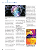
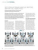
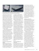
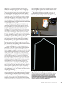
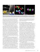
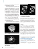
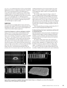
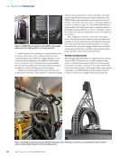
Magnet Wire-Form Fabrication for Bar-Wound Stators
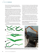
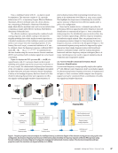
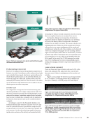
To generate the desired wire-form shape for bar-wound stators,
a spool of insulated copper magnet wire is fed into a forming
machine to first straighten the wire. The wire is then sectioned,
and the insulation coating is removed at the end tips, result-
ing in what is called a magnet wire I-pin. These I-pins then
undergo a multi-stage 3D die-forming process to generate the
hairpin-shaped structures as well as bus connections, as illus-
trated in Figure 2.
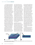
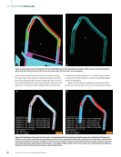
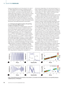
The first set of dies defines the desired two-dimensional
(2D) profile of the wire-form structure, as shown in Figure 2a.
A second set of dies is then applied to generate the full 3D
geometry, as shown in Figure 2b. The resulting “hairpin”
wire-form geometry, shown in Figure 2c, is what is eventu-
ally inserted into the stator core. Figure 2d shows an example
hairpin wire-form produced using this die-forming process
held in a fixture.
To provide a better understanding of the challenges
associated with developing quality-control feedback mea-
surements that can keep pace with production rates typical
for the wire-forming process—while also providing measure-
ments that can accurately assess if the full 3D surface profile
is within the accepted tolerance band for assembly—some
typical values for the wire-forms studied in this paper are
provided here. For the stator assembly used as a reference
in this study, the processing time for producing an individ-
ual hairpin wire-form, such as that shown in Figure 2, is ~1 s.
To make a single stator assembly of the variant used in this
study, a total of 150 wire-forms are inserted into the stator
core. Of these 150 wire-forms, there are seven unique wire-
form geometries that must be analyzed separately in varying
quantities.
Each of the wire-form geometries must adhere to a 3D
surface-profile tolerance of ±0.250 mm across the entire
apex of the hairpin structure. The challenge in developing a
quality-control feedback measurement is that there is often
a trade-off between achieving the measurement accuracy
required over the full 3D surface profile and the time needed to
perform the measurement and provide assessment feedback.
Current Technology for Inspecting Wire-Form Shape
Quality and Limitations
As of today, several automated contact and noncontact
methods exist for performing 3D metrology measurements.
A common automated methodology used in automotive
ME
|
ELECTRICVEHICLES
X
Y
X
Y
X
Y
Z
X
Y
Z
X
Y
Z
Figure 2. (a–c) Illustration examples of the die-forming process that can be used to create magnet wire with the desired shape for bar-wound
electric motor stator assembly (d) example hairpin wire-form component held in a two-leg fixture configuration for examining the apex structure.
36
M AT E R I A L S E V A L U AT I O N • J A N U A R Y 2 0 2 6
the stator slots. As a result, quality-control feedback in the
wire-forming process is crucial for reliably producing electric
motor stator assemblies.
Magnet Wire-Form Fabrication for Bar-Wound Stators
To generate the desired wire-form shape for bar-wound stators,
a spool of insulated copper magnet wire is fed into a forming
machine to first straighten the wire. The wire is then sectioned,
and the insulation coating is removed at the end tips, result-
ing in what is called a magnet wire I-pin. These I-pins then
undergo a multi-stage 3D die-forming process to generate the
hairpin-shaped structures as well as bus connections, as illus-
trated in Figure 2.
The first set of dies defines the desired two-dimensional
(2D) profile of the wire-form structure, as shown in Figure 2a.
A second set of dies is then applied to generate the full 3D
geometry, as shown in Figure 2b. The resulting “hairpin”
wire-form geometry, shown in Figure 2c, is what is eventu-
ally inserted into the stator core. Figure 2d shows an example
hairpin wire-form produced using this die-forming process
held in a fixture.
To provide a better understanding of the challenges
associated with developing quality-control feedback mea-
surements that can keep pace with production rates typical
for the wire-forming process—while also providing measure-
ments that can accurately assess if the full 3D surface profile
is within the accepted tolerance band for assembly—some
typical values for the wire-forms studied in this paper are
provided here. For the stator assembly used as a reference
in this study, the processing time for producing an individ-
ual hairpin wire-form, such as that shown in Figure 2, is ~1 s.
To make a single stator assembly of the variant used in this
study, a total of 150 wire-forms are inserted into the stator
core. Of these 150 wire-forms, there are seven unique wire-
form geometries that must be analyzed separately in varying
quantities.
Each of the wire-form geometries must adhere to a 3D
surface-profile tolerance of ±0.250 mm across the entire
apex of the hairpin structure. The challenge in developing a
quality-control feedback measurement is that there is often
a trade-off between achieving the measurement accuracy
required over the full 3D surface profile and the time needed to
perform the measurement and provide assessment feedback.
Current Technology for Inspecting Wire-Form Shape
Quality and Limitations
As of today, several automated contact and noncontact
methods exist for performing 3D metrology measurements.
A common automated methodology used in automotive
ME
|
ELECTRICVEHICLES
X
Y
X
Y
X
Y
Z
X
Y
Z
X
Y
Z
Figure 2. (a–c) Illustration examples of the die-forming process that can be used to create magnet wire with the desired shape for bar-wound
electric motor stator assembly (d) example hairpin wire-form component held in a two-leg fixture configuration for examining the apex structure.
36
M AT E R I A L S E V A L U AT I O N • J A N U A R Y 2 0 2 6