ABSTR ACT
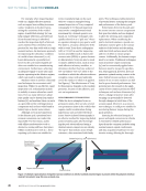
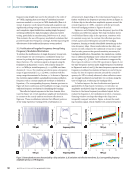
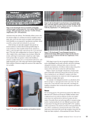
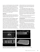
A critical aspect of electric motor fabrication
is the assembly process of the stator winding
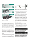
electromagnetic circuit. A common winding
configuration consists of copper magnet wire that
is die-formed into hundreds of complex hairpin
geometric structures, which are then inserted
into a laminate core to form the stator winding.
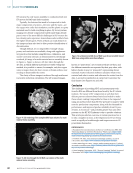
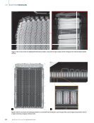
For performance and efficiency, extremely tight
tolerances are required for the wire-form geometries
to avoid improper automated insertion. Quality-
control measurements are increasingly critical
for consistently producing wire-forms that meet
dimensional specifications. However, current
technology capable of accurately measuring these
complex 3D shapes requires far more time than
it takes to produce individual wire-forms, limiting
quality control to only a small number of audits. To
push toward in-process verification in keeping with
the wire-form production rate, significant advances
in data-acquisition strategy and analysis techniques
are necessary. This paper summarizes the noncontact
structured light sensor array system and analysis
methodology developed to allow rapid assessment
of the full 3D wire-form shape. When used in
conjunction with a robust calibration technique, it
becomes feasible to build an in-process inspection
system that can be implemented in production.
KEYWORDS: quality inspection, machine vision,
3D reconstruction, structured light, electric motors
1. Introduction
In recent years, manufacturing has seen an increased adoption
of automation, largely due to advancements in robotics,
modern sensor technology, and data analytical techniques
such as artificial intelligence (AI). These efforts have resulted
in a more data-driven manufacturing environment that aims
to boost plant productivity and improve plant efficiency
while reducing overall costs. Consequently, many traditional
quality-control inspection methods have been replaced by
automatic, nondestructive evaluation (NDE) techniques. One
of the most prolific within manufacturing is the use of machine
vision (Shirmohammadi and Ferrero 2014), which has experi-
enced significant advancements. Sensors coupled to computers
capable of running advanced analytical tools can automatically
extract and analyze useful information from digital representa-
tions of manufactured components.
Machine vision is becoming ubiquitous within industrial
applications for automating real-time inspection for discon-
tinuities (Wang et al. 2017) and providing proactive alerts for
process feedback control (Lee and Kim 2020), whether for
electronic devices (Flack and Hannaford 2005), automotive
products (Wagner and Agapiou 2024), or other components.
Regardless of the application, automated precision machine
vision systems combined with advanced analytical methods
aim to eliminate the need for manual visual inspection on the
production floor. For this reason, there has been an ongoing
effort for industries to acquire tools capable of meeting the
challenges associated with fully automated inspection.
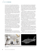
Though there are numerous applications of automated
machine vision within the automotive industry, the global shift
toward electric vehicle (EV) production has placed increased
demand on the precise inspection of battery and electric
motor–related components. Electric motor manufacturing in
particular requires high-fidelity machine vision solutions to
automate quality control along the production line due to its
complex architecture, which becomes increasingly difficult
to assess as it advances toward final assembly. NDE tech-
niques applied to electric motors present unique challenges
that demand rigorous inspection of subassembly components
throughout the fabrication process to ensure they meet the
performance and efficiency demands necessary for vehicle
propulsion.
This paper outlines some of the challenges associated with
implementing fully automated nondestructive quality-control
systems that can perform evaluations at the same pace as the
RAPID IN-PROCESS 3D SHAPE INSPECTION OF
MAGNET WIRE HAIRPINS DURING ELECTRIC
MOTOR ASSEMBLY
SEAN R. WAGNER*
ME
|
TECHPAPER
*Materials &Manufacturing Systems Research Lab, General Motors
Research &Development, 30470 Harley Earl Blvd., Warren MI 48092, USA
(ORCID: 0000-0003-3540-1501) sean.wagner@gm.com
Materials Evaluation 84 (1): 34–44
https://doi.org/10.32548/2026.me-04552
©2026 American Society for Nondestructive Testing
34
M AT E R I A L S E V A L U AT I O N • J A N U A R Y 2 0 2 6
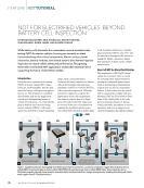
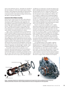
A critical aspect of electric motor fabrication
is the assembly process of the stator winding
electromagnetic circuit. A common winding
configuration consists of copper magnet wire that
is die-formed into hundreds of complex hairpin
geometric structures, which are then inserted
into a laminate core to form the stator winding.
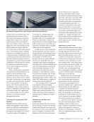
For performance and efficiency, extremely tight
tolerances are required for the wire-form geometries
to avoid improper automated insertion. Quality-
control measurements are increasingly critical
for consistently producing wire-forms that meet
dimensional specifications. However, current
technology capable of accurately measuring these
complex 3D shapes requires far more time than
it takes to produce individual wire-forms, limiting
quality control to only a small number of audits. To
push toward in-process verification in keeping with
the wire-form production rate, significant advances
in data-acquisition strategy and analysis techniques
are necessary. This paper summarizes the noncontact
structured light sensor array system and analysis
methodology developed to allow rapid assessment
of the full 3D wire-form shape. When used in
conjunction with a robust calibration technique, it
becomes feasible to build an in-process inspection
system that can be implemented in production.
KEYWORDS: quality inspection, machine vision,
3D reconstruction, structured light, electric motors
1. Introduction
In recent years, manufacturing has seen an increased adoption
of automation, largely due to advancements in robotics,
modern sensor technology, and data analytical techniques
such as artificial intelligence (AI). These efforts have resulted
in a more data-driven manufacturing environment that aims
to boost plant productivity and improve plant efficiency
while reducing overall costs. Consequently, many traditional
quality-control inspection methods have been replaced by
automatic, nondestructive evaluation (NDE) techniques. One
of the most prolific within manufacturing is the use of machine
vision (Shirmohammadi and Ferrero 2014), which has experi-
enced significant advancements. Sensors coupled to computers
capable of running advanced analytical tools can automatically
extract and analyze useful information from digital representa-
tions of manufactured components.
Machine vision is becoming ubiquitous within industrial
applications for automating real-time inspection for discon-
tinuities (Wang et al. 2017) and providing proactive alerts for
process feedback control (Lee and Kim 2020), whether for
electronic devices (Flack and Hannaford 2005), automotive
products (Wagner and Agapiou 2024), or other components.
Regardless of the application, automated precision machine
vision systems combined with advanced analytical methods
aim to eliminate the need for manual visual inspection on the
production floor. For this reason, there has been an ongoing
effort for industries to acquire tools capable of meeting the
challenges associated with fully automated inspection.
Though there are numerous applications of automated
machine vision within the automotive industry, the global shift
toward electric vehicle (EV) production has placed increased
demand on the precise inspection of battery and electric
motor–related components. Electric motor manufacturing in
particular requires high-fidelity machine vision solutions to
automate quality control along the production line due to its
complex architecture, which becomes increasingly difficult
to assess as it advances toward final assembly. NDE tech-
niques applied to electric motors present unique challenges
that demand rigorous inspection of subassembly components
throughout the fabrication process to ensure they meet the
performance and efficiency demands necessary for vehicle
propulsion.
This paper outlines some of the challenges associated with
implementing fully automated nondestructive quality-control
systems that can perform evaluations at the same pace as the
RAPID IN-PROCESS 3D SHAPE INSPECTION OF
MAGNET WIRE HAIRPINS DURING ELECTRIC
MOTOR ASSEMBLY
SEAN R. WAGNER*
ME
|
TECHPAPER
*Materials &Manufacturing Systems Research Lab, General Motors
Research &Development, 30470 Harley Earl Blvd., Warren MI 48092, USA
(ORCID: 0000-0003-3540-1501) sean.wagner@gm.com
Materials Evaluation 84 (1): 34–44
https://doi.org/10.32548/2026.me-04552
©2026 American Society for Nondestructive Testing
34
M AT E R I A L S E V A L U AT I O N • J A N U A R Y 2 0 2 6