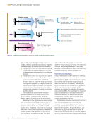
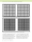
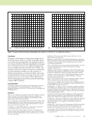
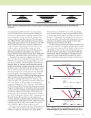
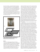
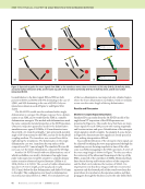
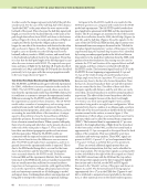
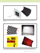
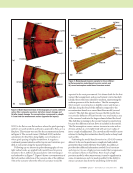
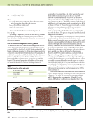
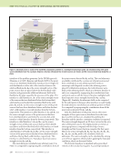
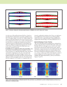
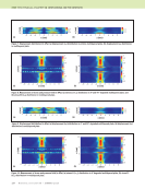
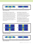
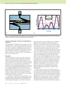
102 M A T E R I A L S E V A L U A T I O N • J A N U A R Y 2 0 2 0 Challenges of Implementing NDE Models in a CAD Context Implementing an NDE model often involves iterating or inte- grating over part or all of the specimen. For flat, rectangular 2D parts, we can easily iterate over a regular grid with uniform step sizes. It is straightforward to integrate over surface and over volume as needed. If there is experimental data, it would be defined on the same grid. Implementing an NDE model in a CAD context is signifi- cantly more difficult. First, the NDE model itself may be significantly more complicated in the above example of ther- mography model-based inversion a new theory was needed to represent differences in propagation along curved surfaces. Second, the NDE model will need access to geometric infor- mation such as curvatures and/or ray intersections. Third, iteration and integration become significantly more difficult. Iterating or integrating over a 3D CAD volume requires constructing a volumetric mesh—a nontrivial operation. In most cases, the mesh will contain faces that don’t line up with the coordinate axes and thus are harder to work with. A simpler voxel (regular) grid will line up to coordinate axes, but will give poor, jagged boundaries wherever the object boundary fails to line up with the coordinate frame. Either case adds an order of magnitude of complexity compared to volume integrals over flat objects. Iterating or integrating over surfaces in a CAD context is also nontrivial. The surface parameterizations, such as illus- trated in Figure 3c, provide a domain for the iteration or inte- gration. A surface integral can be performed by integrating over a regular grid in the parameterization space, subject to a few caveats. A “conformal” parameterization ensures that the (du, dv) increment in parameterization space will correspond to a little rectangle on the physical surface. If the parameterization is a “development” (Kreysig 1991) of a physical surface that is “developable,” then that little rectangle will be the same size everywhere on the object otherwise, the NDE model will need to accommodate differences in scaling across the para- meterization space. The presence of artificial boundaries and seams in the parameterization can also present a challenge because jagged edges in parameterization space lead to incorrect integration. Referring again to Figure 3c, the parameterization is necessarily broken up into multiple pieces. Where the bound- aries of the pieces do not coincide with the u and v axes of the parameterization, there will be (du, dv) increments (pixels of the parameterization) that cross the boundary. For these pixels, the physical area is smaller than du × dv. Depending on the nature of the integration, the reduced area may be significant. Another challenge is that physically adjacent points on the surface may be separated in the parameterization by a seam or boundary. Many algorithms, including the model-based inversion discussed in this paper, need to consider nearby locations, not just the point of integration. Ideally the algo- rithm would be able to look across a nearby boundary and pull data from elsewhere in the parameterization as needed. Our current thermography model-based inversion implemen- tation does not yet have this capability, and instead requires surfaces that can have significant lateral heat flow be intact in the parameterization, not broken by a seam or boundary. Open Source spatialnde and spatialnde2 Software Libraries Clearly, both projecting data into a CAD context and imple- menting NDE models in that context are nontrivial. While some of the steps, such as 3D raytracing projections, are not substantively innovative from a computer graphics stand- point, they are nevertheless nontrivial to implement. If we want to be able to better leverage CAD solid models in NDE data analysis and simulation, better software tools are needed to simplify projection, raytracing, access to geometric infor- mation, and iteration/integration. These tools need to be readily available to both academia and industry. The prototype geometry management library used for the work described here is known as spatialnde. The prototype is written in Python and is published as open source at https://github.com/isuthermography/spatialnde, but as a prototype it is not very suitable for industrial-strength problems. A successor package, spatialnde2, is available at https://thermal.cnde.iastate.edu/spatialnde2.xhtml. The successor is written in C++ based on the lessons learned in the work described in this paper. It is designed to help NDE models interface with geometry. It is designed to be usable from both compiled languages and interpreted languages, support concurrency, GPU acceleration for both raytracing and NDE modeling operations, multiple geometric objects, and caching of geometry and/or data in GPU memory. As of this writing, it is not yet complete, but major portions of func- tionality are in place and working. It is hoped that the spatialnde2 library will help the whole community better leverage modeling and open up new research opportunities both in the development and use of NDE models. Summary and Conclusion The use of a 3D CAD model context allows the use of signifi- cantly more sophisticated data analysis codes, because the knowledge of geometry includes critical characteristics such as surface curvature. Techniques and approaches for modeling in the context of a 3D CAD model are quite broadly appli- cable across NDE modalities. We used a recently developed thermography model-based inversion algorithm to illustrate the use of CAD modeling in NDE data inversion. We described the process of registering the NDE data (thermography images) to the CAD model and the creation of a surface parameterization. The parameterization provides a two-dimensional domain in which to perform data analysis and fusion. We described how relating experimental data to ME TECHNICAL PAPER w nde modeling in 3d cad

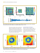
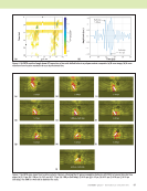
J A N U A R Y 2 0 2 0 • M A T E R I A L S E V A L U A T I O N 103 CAD-driven models of the NDE process helped improve understanding of the measurement physics (sensitivity to illu- mination gradients). Two variants of a model-based inversion code for pulse thermography were described. Both variants require the thermal images registered to the CAD model onto the physical part. The first variant neglects the effect of curvature on heat flow physics, whereas the second model uses a proper model of heat flow for curved media, using curvatures extracted from the CAD geometry. The second model gives better results in some cases at sharp bends, but for the most part the two models generate a very similar output. Performing NDE data analysis and modeling in 3D CAD context can be beneficial. Significantly more sophisticated inversion algorithms are possible when geometric data is avail- able. In addition, creating the 2D surface parameterization needed to map many types of data onto the CAD model also creates a suitable domain for data fusion and “digital thread” or “digital twin” databases of NDE data. More research is needed, particularly for ways to accommodate geometric inconsistency and for better ways to define persistent surface parameterizations. Working with 3D CAD geometry is still far too compli- cated to be practicable for most practicing NDE scientists and engineers. The forthcoming open source spatialnde2 library will hopefully begin to address some of those challenges and enable a new generation of NDE models and inversion algo- rithms that can accommodate real geometries and take advan- tage of geometric knowledge. ACKNOWLEDGMENTS Portions of this research were funded by NASA Early Stage Innovation under award NNX15AD75G. Portions of this research were funded by TRI-Austin under an AFRL SBIR, clearance #88ABW-2019-4360. Portions of this research were funded by the Iowa State University Center for NDE Industry/University Cooperative Research Center program. REFERENCES Blender Online Community, 2017, Blender - A 3D modeling and rendering package, version 2.79, available at https://www.blender.org. Bradski, G., 2000, “The OpenCV Library,” Dr. Dobb’s Journal of Software Tools, Vol. 25, pp. 120–123. Calmon, P., S. Mahaut, S. Chatillon, and R. Raillon, 2006, “CIVA: An Expertise Platform for Simulation and Processing NDT Data,” Ultrasonics, Vol. 44, pp. 975–979. Cornwell, I., and A. McNab, 1999, “Towards Automated Interpretation of Ultrasonic NDT Data,” NDT&E International, Vol. 32, No. 2, pp. 101–107. Frishman, A., and S.D. Holland, Forthcoming, “Calculation of Green’s Functions for Heat Conduction in Curved Anisotropic Media,” in preparation. Holland, S. D., 2018, Greensinversion model based inversion software, available at https://thermal.cnde.iastate.edu/greensinversion.xml. Holland, S. D., and B. Schiefelbein, 2019, “Model-based Inversion for Pulse Thermography,” Experimental Mechanics, Vol. 59, No. 4, pp. 413–426. Holland, S. D., 2018, Heatsim2, a package for finite difference calculations of heat conduction, available at http://thermal.cnde.iastate.edu/heatsim2 .xml. Holland, S. D., Forthcoming, “Model-based Inversion for Pulse Thermog- raphy in Curved Media,” in preparation. Kreyszig, E., 1991, Differential Geometry, Dover Publications, New York, NY. Kundu, T., D. Placko, E.K. Rahani, T. Yanagita, and C.M. Dao, 2010, “Ultrasonic Field Modeling: A Comparison of Analytical, Semi-Analytical, and Numerical Techniques,” IEEE Transactions on Ultrasonics, Ferro- electrics, and Frequency Control, Vol. 57, No. 12, pp. 2795–2807. Lévy, B., S. Petitjean, R. Nicolas, and J. Maillot, 2002, “Least Squared Conformal Maps for Automatic Texture Atlas Generation,” ACM Transac- tions on Graphics, Vol. 21, No. 3, pp. 362–371. Lonné, S., L. de Roumilly, L. Le Ber, S. Mahaut, and G. Cattiaux, 2006, “Experimental Validation of CIVA Ultrasonic Simulations,” International Conference on NDE in Relation to Structural Integrity for Nuclear and Pressurized Components, San Diego, CA. Ludwig, R., and W. Lord, 1988, “A Finite-Element Formulation for the Study of Ultrasonic NDT Systems,” IEEE Transactions on Ultrasonics, Ferroelectrics, and Frequency Control, Vol. 35, No. 6, pp. 809–820. Maldague, X., 2001, Theory and Practice of Infrared Technology for Nonde- structive Testing, John Wiley and Sons, New York, NY. Moser, F., L.J. Jacobs, and J. Qu, 1999, “Modeling Elastic Wave Propaga- tion in Waveguides with the Finite Element Method,” NDT&E Interna- tional, Vol. 32, No. 4, pp. 225–234. Newberry, B.P., and R.B. Thompson, 1989, “A Paraxial Theory for the Propagation of Ultrasonic Beams in Anisotropic Solids,” The Journal of the Acoustical Society of America, Vol. 85, No. 6, pp. 2290–2300. Radkowski, R., S. Holland, and R. Grandin, 2018, “Evaluation of the Fidelity of Feature Descriptor-Based Specimen Tracking for Automatic NDE Data Integration,” AIP Conference Proceedings, Vol. 1949, No. 1, doi: 10.1063/1.5031531. Sabbagh, H.A., R.K. Murphy, E.H. Sabbagh, J.C. Aldrin, and J.S. Knopp, 2013, Computational Electromagnetics and Model-Based Inversion: A Modern Paradigm for Eddy-Current Nondestructive Evaluation, Springer-Verlag, New York, NY. Shepard, S.M., J. Hou, J.R. Lhota, and J. Golden, 2007, “Automated Processing of Thermographic Derivatives for Quality Assurance,” Optical Engineering, Vol. 46, No. 5, doi: 10.1117/1.2741274. Steffes, G., J. Shearer, S. Turek, W. Fong, T. Sharp, and G. Coyan, 2012, “Aircraft Management and Sustainment Using NDI Data Trending and Mapping Technologies,” Aircraft Structural Integrity Program, San Antonio, TX. Tuegel, E.J., A.R. Ingraffea, T.G. Eason, and S.M. Spottswood, 2011, “Reengineering Aircraft Structural Life Prediction Using a Digital Twin,” International Journal of Aerospace Engineering, Vol. 2011, No. 154798. Zombo, P.J., and R.E. Shannon, 2006, “Advanced NDE Systems for Flexible Operation and Maintenance of Gas Turbine Components,” PowerGen International, Orlando, FL.
ASNT grants non-exclusive, non-transferable license of this material to  .
All rights reserved. © ASNT 2026. To report unauthorized use, contact: customersupport@asnt.org