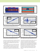
94 M A T E R I A L S E V A L U A T I O N • J A N U A R Y 2 0 2 0 Bar-Cohen, Y., and R. Crane, 1982b, “Nondestructive Evaluation of Fiber- Reinforced Composites with Acoustic Backscattering Measurements,” ASTM International, West Conshohocken, PA. Boll, D.J., W.D. Bascom, J.C. Weidner and W.J. Murri, 1986, “A Microscopy Study of Impact Damage of Epoxy-Matrix Carbon-Fibre Composites,” Journal of Materials Science, Vol. 21, No. 8, pp. 2667–2677. Christian, W., E. Patterson, and F. DiazDelaO, 2017, “Robust Empirical Predictions of Residual Performance of Damaged Composites with Quan- tified Uncertainties,” Journal of Nondestructive Evaluation, Vol. 36, doi: 10.1007/s10921-017-0416-6. Daniel, I.M., and O. Ishai, 2006, Engineering Mechanics of Composite Mate- rials, Oxford University Press, New York, NY. Flores, M.D., 2016, “Damage Tolerance and Assessment of Unidirectional Carbon Fiber Composites: An Experimental and Numerical Study,” Disser- tation Abstracts International, Vol. 77–11(E), p. 274. Gosse, J.H., and L.R. Hause, 1988, “A Quantitative Nondestructive Evalua- tion Technique for Assessing the Compression-After-Impact Strength of Composites Plates,” Review of Progress in Quantitative Nondestructive Evalu- ation, Vol. 7b, pp. 1011–1020. Gosse, J.H., and S.M., Sorscher, 1989, “An Integrated Damage Analysis of Laminated Composite Plates,” Review of Progress in Quantitative Nonde- structive Evaluation, Vol 8, pp. 1651–1655. Guild, F.J., N. Vrellos, B.W. Drinkwater, N. Balhi, S.L. Ogin, and P.A. Smith, 2006, “Intra-Laminar Cracking in CFRP Laminates: Observations and Modelling,” Journal of Materials Science, Vol. 41, No. 20, pp. 6599–6609. Homa, L., D. Sparkman, J. Wertz, J. Welter, and J. C. Aldrin, 2018, “Signal Decomposition for Surrogate Modeling of a Constrained Ultrasonic Design Space,” AIP Conference Proceedings, Vol. 1949, No. 1. Johnston, P.H., C.D. Appleget, and M.T. Odarczenko, 2013, “Characteriza- tion of Delaminations and Transverse Matrix Cracks in Composite Lami- nates Using Multiple-Angle Ultrasonic Inspection,” AIP Conference Proceedings, Vol. 1511, No. 1. Kersemans, M., A. Martens, K. Van Den Abeele, J. Degrieck, L. Pyl, F. Zastavnik, H. Sol, and W. Van Paepegem, 2015, “The Quasi-Harmonic Ultrasonic Polar Scan for Materials Characterization: Experiment and Numerical Modeling,” Ultrasonics, Vol. 58, pp. 111–122. Kersemans, M., I. De Baere, J. Degrieck, K. Van Den Abeele, L. Pyl, F. Zastavnik, H. Sol, and W. Van Paepegem, 2014a, “Nondestructive Damage Assessment in Fiber Reinforced Composites with the Pulsed Ultrasonic Polar Scan,” Polymer Testing, Vol. 34, pp. 85–96. Kersemans, M., W. Van Paepegem, B. Lemmens, K. Van Den Abeele, L. Pyl, F. Zastavnik, H. Sol, and J. Degrieck, 2014b, “The Pulsed Ultrasonic Backscatter Polar Scan and its Applications for NDT and Materials Charac- terization,” Experimental Mechanics, Vol. 54, No. 6, pp. 1059–1071. Kersemans, M., I. De Baere, J. Degrieck, K. Van Den Abeele, L. Pyl, F. Zastavnik, H. Sol, and W. Van Paepegem, 2014c, “Damage Signature of Fatigued Fabric Reinforced Plastics in the Pulsed Ultrasonic Polar Scan,” Experimental Mechanics, Vol. 54, No. 8, pp. 1467–1477. Lopez-Sanchez, A.L., H.-J. Kim, L.W. Schmerr Jr., and A. Sedov, 2005, “Measurement Models and Scattering Models for Predicting the Ultrasonic Pulse-Echo Response from Side-Drilled Holes,” Journal of Nondestructive Evaluation, Vol. 24, No. 3, pp. 83–96. Martens, A., M. Kersemans, J. Daemen, E. Verboven, W. Van Paepegem, J. Degrieck, S. Delrue, and K. Van Den Abeele, 2017, “Numerical Study of the Time-of-Flight Pulsed Ultrasonic Polar Scan for the Determination of the Full Elasticity Tensor of Orthotropic Plates,” Composite Structures, Vol. 180, pp. 29–40. Michaels, J.E., T.E. Michaels, and B. Mi, 2006, “An Ultrasonic Angle Beam Method for in Situ Sizing of Fastener Hole Cracks,” Journal of Nondestruc- tive Evaluation, Vol. 25, No. 1, pp. 2–15. Mollenhauer, D., E. Iarve, K. Hoos, M. Flores, E. Zhou, E. Lindgren, and G. Schoeppner, 2016, “Damage Tolerance for Life Management of Composite Structures - Part 1: Modeling,” Aircraft Structural Integrity Program Conference, San Antonio, TX. Reverdy, F., S. Mahaut, N. Dominguez, and P. Dubois, 2015, “Simulation of Ultrasonic Inspection of Curved Composites Using a Hybrid Semi- Analytical/Numerical Code,” AIP Conference Proceedings, Vol. 1650, No.1. US Department of Defense, 2009, Nondestructive Evaluation System Reliability Assessment, MIL-HDBK-1823A. Van Dreumel, W.H., and J.L. Speijer, 1981, “Nondestructive Composite Laminate Characterization by Means of Ultrasonic Polar-Scan,” Materials Evaluation, Vol. 39, pp. 922–925. Welter, J.T., J.N. Wertz, J.C. Aldrin, V. Kramb, and D. Zainey, 2018, “Model-Driven Optimization of Oblique Angle Ultrasonic Inspection Parameters for Delamination Characterization,” AIP Conference Proceed- ings, Vol. 1949, No. 1. Wertz, J., L. Homa, D. Sparkman, J. Welter, and J. C. Aldrin, 2018, “Gaussian Process Regression of Chirplet Decomposed Ultrasonic B-scans of a Simulated Design Case,” in Review of Progress in Quantitative Nondestructive Evaluation, AIP Conference Proceedings 1949, 130007-1–130007-9. ME TECHNICAL PAPER w angle-beam pulse-echo ultrasonic inspection

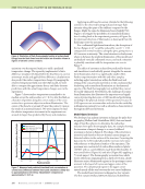
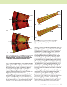
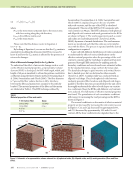
J A N U A R Y 2 0 2 0 • M A T E R I A L S E V A L U A T I O N 95 ME TECHNICAL PAPER w A B S T R A C T Nondestructive evaluation (NDE) modeling and analysis codes have traditionally been developed for oversimplified geometries such as flat plates. This is partly because simple geometries are easier to work with, but also partly because the tools needed for NDE scientists and engineers to easily work with real geometries have not been available. Modeling and analysis in physical geometric contexts can be more accurate because the geometry can be included in the analysis. In addition, the models naturally align with emerging “digital thread” and “digital twin” concepts for maintaining parallel digital models of entire struc- tures. In this paper we describe an analysis process for pulse (flash) thermography NDE that operates in the physical 3D computer-aided design (CAD) geometry of the underlying part. We also discuss how the thermography problem motivated the development of a new open-source library (“spatialnde2”) designed to facilitate the use of 3D CAD geometry in NDE modeling and analysis. Using pulse thermography as an example, we discuss the benefits and challenges of performing data analysis in the 3D CAD domain. KEYWORDS: pulse thermography, NDE modeling, NDT modeling, NDE data analysis, model-based inversion, CAD modeling Introduction The modern era of quantitative nondestructive evaluation was made possible by the use of physical and statistical models to understand the result of an NDE inspection. The earliest models were quite simple, and most data analysis, even today, is based on very simple ideas such as mapping time to distance. The modeling work of the last half century combined with the advent of modern computing power offers the prospect of fast, automatic analysis tailored to the unique characteristics of the location under test (Cornwell and McNab 1999). Modern modeling approaches, whether based on finite elements (Ludwig and Lord 1988 Moser et al. 1999), raytraced beam models (Newberry and Thompson 1989), or semi-analytical approximations (Kundu et al. 2010 Calmon et al. 2006) can accurately predict NDE signals (Lonné et al. 2006). In many cases these models can be operated in reverse to improve analysis (Sabbagh et al. 2013), but such inversion is usually either specific to certain geometries or requires an accurate geometric model (Holland and Schiefelbein 2019). Model-based inversion has the potential to give better output than traditional approaches because of the additional a priori knowledge. Steps other than analysis in the NDE workflow, such as model-based design and model-based POD, can be improved through modeling as well. It will become possible to seamlessly feed all NDE measurements into a CAD-based “digital thread” to perform “digital twin” analysis of the condition of the part (Tuegel et al. 2011). A number of technological improvements will be required to support model-based NDE. First, the ability to know the geometric position and orientation (“pose”) of the sensor and specimen during acquisition, so that the NDE data can be regis- tered to the physical specimen. Second, the ability for NDE modeling codes to utilize the known geometry. And third, the ability to accommodate geometric differences. The first problem, registration, is not exactly new, and solutions for geometric regis- tration have been around for a long time. Pioneering work by Siemens Energy (Zombo and Shannon 2006) mapped turbine blade inspection data onto CAD models. Etegent’s NLign product (Steffes et al. 2012) is used to store NDE data in geometric context. Nevertheless, geometric registration of NDE data to CAD models has remained difficult enough that it has been rare in practice. The second problem, integrating NDE modeling codes with CAD models, is solved in some contexts, such as commercial packages like CIVA (Calmon et al. 2006), but remains out of reach for the vast majority of scientists who develop NDE modeling codes. The final problem, geometric inconsistency, remains unsolved. NDE Data Analysis and Modeling in 3D CAD Context by Stephen D. Holland*, Chevonne McInnis†, Rafael Radkowski†, and Adarsh Krishnamurthy† * Center for Nondestructive Evaluation, Iowa State University, Ames, IA sdh4@iastate.edu 515-294-8659 fax 515-294-7771 † Center for Nondestructive Evaluation, Iowa State University, Ames, IA
ASNT grants non-exclusive, non-transferable license of this material to  .
All rights reserved. © ASNT 2026. To report unauthorized use, contact: customersupport@asnt.org