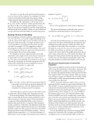
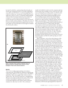
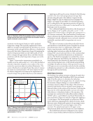
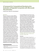
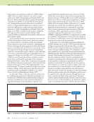
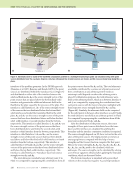
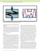
82 M A T E R I A L S E V A L U A T I O N • J A N U A R Y 2 0 2 0 ME TECHNICAL PAPER w A B S T R A C T Model benchmark studies are presented for angled-beam inspections of composites to validate the performance of two promising models. However, manual interpretation of the signal response can be quite complicated, even for inspection of side-drilled holes in a thin composite. The use of models is introduced in this paper to guide this complex signal interpretation task. Specifically, wave maps are used to illustrate the complexity of the oblique-angle ultrasound propagation in these layered anisotropic materials. For the two benchmark cases presented, each model provided the closest estimates of location and time of flight return signals for one case or the other, indicating neither model is clearly better for this specific case. In fact, it will be shown that the two models provide complimentary information in the case of angled-beam inspections of compos- ites. Lastly, simulated results from both single and hidden delamination scenarios are studied, and contrasted with side-drilled hole benchmarking results, providing critical insight into optimization of the angle-beam pulse-echo inspection technique for characterizing hidden delaminations from a single side. KEYWORDS: ultrasound, modeling, polymer matrix composites Introduction Current practical nondestructive evaluation (NDE) tech- niques and methods to evaluate impact damage in polymer matrix composites (PMCs) focus on detection, while also providing estimates of the spatial dimensions from image indi- cations. Most techniques involve directly applying metallic structure NDE techniques to PMCs. This approach has served the community well for many years but needs for aero- space structures with ever increasing performance require- ments challenge this status quo. All PMC parts are currently designed with the safe-life philosophy. This results in parts with substantial safety margins that are thereby heavier than parts designed for damage tolerance. For aerospace structures, weight directly impacts capability, affecting fuel efficiency, cargo capacity, and cruise speed. A key point is that safety is ensured in damage tolerance by one of three approaches: (1) slow crack growth (2) fail-safe multiple load paths or (3) fail-safe crack arrest (Babish 2008). The risk of structural failure stays the same or improves when damage tolerance is applied properly (Babish 2008). In the case of slow crack growth, probabilistic material behavior models (Mollenhauer et al. 2016) and statistically verified NDE (US Department of Defense 2009) with quantified uncertainties (Christian et al. 2017) based on a comprehensive understanding of material- degradation behavior are necessary. For damage tolerance using the slow crack-growth criteria, the factor of safety is merely shifted from incorporating it in the part design to incorporating it within part sustainment. The challenge with implementing damage tolerance for PMCs is that they exhibit damage differently than metals. Specifically, the nature and complexity of impact damage in comparison to metallic structures is not perfectly understood. The literature has examples that try to illustrate this complexity, such as Flores (2016), Gosse and Hause (1988), Gosse and Sorscher (1989), and Abrate (1998). It is clear from the literature that there are many factors that affect the morphology of a delamination field, and the profile in depth can vary a great deal, as shown in Figure 1. In the most general sense, the delamination field can be thought of as a series of distorted pie slice –shaped ply separations spaced throughout the thickness of the laminate, with connecting-matrix cracks Model Benchmarking Studies of Angle-Beam Pulse-Echo Ultrasonic Inspection of Composites by John T. Welter*, John C. Aldrin†, John N. Wertz‡, Victoria Kramb§, and David Zainey§ *Materials State Awareness Branch, AFRL/RXCA, Wright-Patterson AFB, OH 45433 john.welter.2@us.af.mil †Computational Tools, Gurnee, IL 60031 ‡ Materials State Awareness Branch, AFRL/RXCA, Wright-Patterson AFB, OH 45433 §University of Dayton Research Institute, Dayton, OH 45469

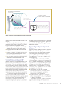
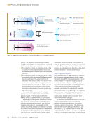
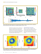
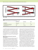
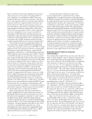
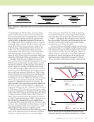
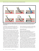
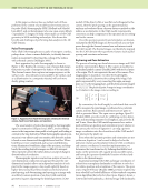
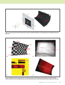
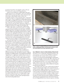
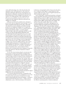
J A N U A R Y 2 0 2 0 • M A T E R I A L S E V A L U A T I O N 83 oriented along the ply fiber directions. Each succeeding pattern of delaminations rotates downward, resulting in a transition from delaminations being fully visible to hidden. Impact-damaged composites are typically inspected with normal-incidence longitudinal ultrasound. By utilizing the time of flight (TOF) and the longitudinal wave speed in the material, the depth and extent of a discontinuity can be deter- mined. Often this inspection is done from a single side to avoid removing a component from service. However, this results in only non-occluded delamination areas being imaged, which results in large regions of the delamination field remaining unknown, especially for cases shown in Figures 1b and 1c (Flores 2016 Gosse and Hause 1988 Gosse and Sorscher 1989 Abrate 1998 Lopez-Sanchez et al. 1998). An angled-beam ultrasonic technique is proposed to detect and characterize such hidden damage in quasi-isotropic PMCs from an external surface using quasi-shear waves, by both direct (solid line) and reflected paths (dashed lines) as shown in Figure 2a. Currently, models that can accurately simulate the scattering of oblique ultrasound from canonical geometries, such as side-drilled holes in homogeneous mate- rials, are still being optimized (Michaels et al. 2006). Sizing defects in homogeneous materials from an angle-beam ultra- sound inspection is also ongoing (Kersemans et al. 2015). Developing the same level of fidelity for modeling and sizing defects in quasi-isotropic layered materials such as PMC materials is a challenge that remains to be overcome. The angle-beam pulse-echo approach presented here builds upon prior work on polar-backscatter ultrasonic techniques for composites (Martens et al. 2017 Aldrin et al. 2018 Welter et al. 2018 Reverdy 2015). Recently, there have been a number of papers investigating the use of variations of ultrasonic polar scans for detection of damage (Daniel and Ishai 2006 Boll et al. 1986 Bar-Cohen and Crane 1982a, 1982b Guild et al. 2006), and for material-property characterization (Johnston et al. 2013 Vandreumel and Speijer 1981). A large portion of this work has been demonstrated on only unidirectional, cross-ply, and fabric composites (Boll et al. 1986 Bar-Cohen and Crane 1982a, 1982b Guild et al. 2006 Johnston et al. 2013 Vandreumel and Speijer 1981), and it remains to be seen if it will be validated on quasi-isotropic composites as well. Recently, several researchers have been addressing various aspects of the angle-beam pulse-echo ultrasonic inspection problem in composites (Kersemans et al. 2014a 2014b 2014c Homa et al. 2018 Wertz et al. 2018). In particular, many of the fundamentals of inspecting for hidden delamina- tions with oblique ultrasound are described by Kersemans et al. (2014a). Conceptually, this technique has been shown to have the possibility of interacting with delaminations that are otherwise occluded when using a normal incident longitu- dinal ultrasonic wave (Homa et al. 2018). One key challenge in utilizing the angled-beam pulse-echo inspection technique is resolving the multiple signals scattered from delamination edges at different depths, shown schemati- cally in Figure 2a. Because the scattered signals will interact with the composite panel surfaces and possibly neighboring delaminations, manual interpretation of the paths for each signal can be quite complicated (Kersemans et al. 2014a). The use of models, in particular wave maps, is introduced in Figure 1. Schematics of delamination field cross sections based on results presented in previous research: (a) cone (b) inverted cone (c) diamond. (a) (b) (c) Top/near surface Top/near surface Bottom/far surface Bottom/far surface Side-drilled hole Delamination edge Legend Full skip Half skip Direct y x y x Legend Full skip Half skip Direct Figure 2. Multiple paths of selected diffracted signals from: (a) a delamination edge (b) a side-drilled hole (Kersemans et al. 2014a). (a) (b)
ASNT grants non-exclusive, non-transferable license of this material to  .
All rights reserved. © ASNT 2026. To report unauthorized use, contact: customersupport@asnt.org