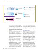
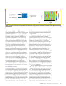
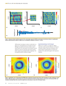
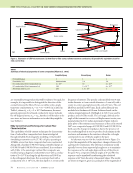
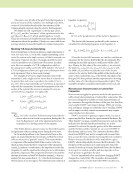
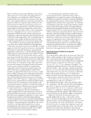
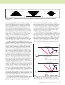
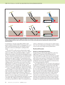
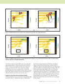
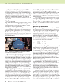
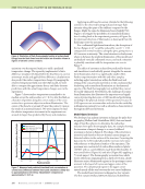
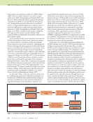
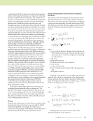
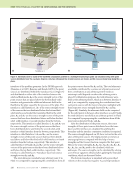
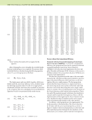
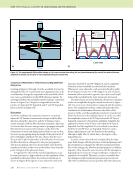
42 M A T E R I A L S E V A L U A T I O N • J A N U A R Y 2 0 2 0 Figure 2. The augmented signal strategy consists of merging a flawless signal with a flaw signature. Regarding the flawless signal, two options have been considered: l The inspection is done on a structure mock-up that is made of the real targeted material. In this case, the flawless signal is acquired live on the inspected structure. l The inspection is done on a structure mock-up that is not made of the real material. The flawless signal has to be simulated. This option might be of interest to lower the cost of the mock-up or to have a more generic setup able to change (virtually) the material using the same mock-up. In this case, the trickiest element of the simulation is the realistic structural noise simulation, for which we later also describe a model. The results of the operational NDT simulator prototype presented in the results section of this paper are based on the first option, where the flawless signal is acquired live on the real material. Regarding the flaw signature, usual wave propaga- tion solvers are not fast enough to comply with the real-time requirements. For instance, very fast semi- analytical solvers like the ones available in CIVA (Calmon et al. 2006) need around 100 ms to compute an A-scan. To avoid slow computations, a database of already measured flaw signatures can be collected and played back during the inspection. This option reduces the number of possible scenarios since a database should be built prior to each new inspection condition. The prototype developed in this study proposes an original approach based on a data-driven synthesis (Rodat et al. 2018a), presented next. Defect Response Simulation A typical defect found in CFRP material is a delamina- tion. Composite materials reference blocks contain flat-bottom holes (FBH) of several diameters to check for the ability of UT inspection setups to properly detect such defects in the material. Therefore, as a proof of concept, we have focused on the simulation of FBH responses so that the operational NDT simulator can simulate the inspection of composite parts containing FBHs. The geometry of the inspected part is, for now, limited to a locally flat area with a constant thickness. In the future, more advanced models will be studied in order to simulate more realistic delamination damages. The developed simulation technique is based on a meta-modeling approach that requires a prior database of known flaw signatures, captured by scanning a typical reference block. The meta-model takes the FBH diameter f, the part thickness e, and the position (xp, yp) of the probe as the input. The output is the flaw signature in our case, the fragment of A-scan containing the defect echo and the backwall ME FEATURE w operational ndt simulations Flawless signal Time (t) Flaw signature Time (t) Augmented signal Time (t) Acquire signals from the mock-up Mock-up made of composite Mock-up made any other material Wave propagation solvers (time-consuming) Data-driven synthesis Database of already measured defects (limited genericity) Synthesize the signal Real signals used as is Synthesis of the microstructure effect Merge the flawless signal and the flaw signature Figure 2. Augmented signal applied to ultrasonic testing and the investigated options. Amplitude Amplitude Amplitude

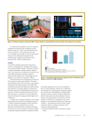
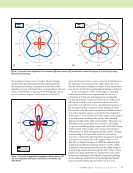
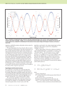
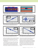
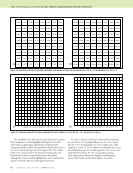
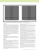
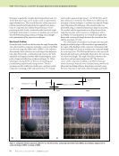
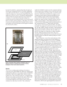
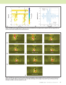
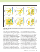
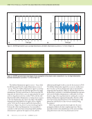
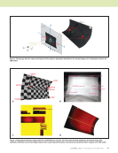
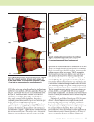
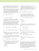
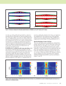
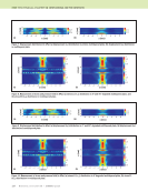
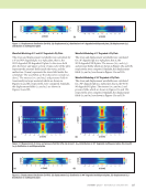
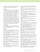
J A N U A R Y 2 0 2 0 • M A T E R I A L S E V A L U A T I O N 43 echo as shown in Figure 3. The prior database contains flaw signatures acquired on a reference block with FBH of diameters 4, 6, 7, 8, 9, 12, and 16 mm and material thicknesses of 7.2, 14.5, and 21.8 mm. The FBH are drilled at 1 mm of the backwall of the material. All the flaw signatures are compressed to reduce the dimension of the output vectors and to enhance the computation speed of the meta-model. The adopted compression technique is based on the orthogonal matching pursuit (Pati et al. 1993), which gives a high compression ratio and manages the compression of flaw signatures corresponding to different FBH depths. Regarding the meta-modeling approach, ordinary kriging (Rasmussen and Williams 2006) is well suited to this problem both in terms of output vector dimension and computation speed. A modification of the kriging algorithm is developed in this work to integrate a physical model into the corre- lation function. For more details on this aspect, the reader can refer to previous research (Rodat et al. 2018b). This technique enhances the meta-model by mixing information from the database of real signals with a model describing the FBH response. The constructed meta-model outputs an A-scan in less than 1 ms. This model has been implemented into the prototype presented in the results section of this paper. Structural Noise Simulation As previously described, to enhance the flexibility of the operational NDT simulator, it can be of interest to consider a mock-up made of any other material. For instance, the mock-up can be made of wood or plastic and the ultrasound signals must look like the ones acquired from a CFRP part. Under the assumption of a locally flat part with a constant thickness, the flawless signal is affected only by the CFRP microstructure. The simulation of this effect, also known as structural noise, raises two issues: the fine description of the microstructure entails time-consuming computations, and the characterization of this microstructure is not always available. The proposed solution here is to learn the struc- tural noise from real signals. To do so, texture synthesis algorithms developed in the computer vision domain have been investigated. By analogy, we will speak about “ultrasonic texture.” The ultrasonic texture is made of a deterministic pattern due to the fiber strands’ orientation and is affected by random distortions induced by the manufacturing process. In this approach, ultrasonic textures are mathematically represented by a random field with spatial correla- tions. Following texture synthesis algorithms, the statistical characteristics of the random field are extracted from a small sample, and an equivalent field can be simulated in a larger area. Different algorithms are available: some are specific to a given type of visual texture, such as wooden material, and cannot be easily adapted to ultrasound data some are based on a gaussian random field assumption and some others make use of the Markov random field assump- tion. The ultrasonic texture does not necessarily show gaussian properties, so the Markov-based techniques are chosen. The implemented algorithm is adapted from Efros and Leung (1999). First, the ultrasonic texture is acquired over a small CFRP sample, giving a reference texture. In the present study, the reference texture covers a 70 mm × 70 mm area. Then, the texture synthesis algorithm is initial- ized with a random and large texture. For instance, 140 mm × 140 mm is used in the case of Figure 4. After initialization, a neighborhood correction similar to Dong et al. (2008) is applied to the texture: each synthesized pixel is drawn among the pixels of the reference texture that have a similar neighborhood. The resulting synthesized texture shows the same patterns as the small reference texture. From a small Part thickness e Meta-model FBH ultrasound signature s (t) Probe position (x p , y p ) FBH diameter φ 1 1.5 20 0 –1 t (μs) Figure 3. Description of the meta-model approach for flat-bottom hole (FBH) signatures: (a) flowchart (b) example of flaw signatures at various probe positions. (b) (a) x(mm) p Amplitude (a.u.)
ASNT grants non-exclusive, non-transferable license of this material to  .
All rights reserved. © ASNT 2026. To report unauthorized use, contact: customersupport@asnt.org