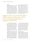
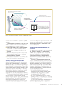
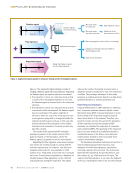
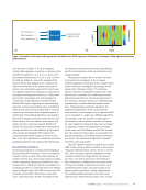
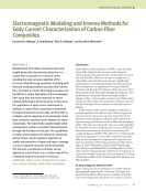
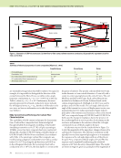
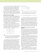
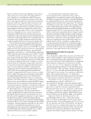
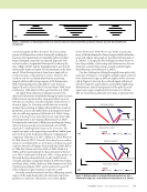
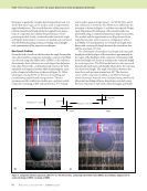
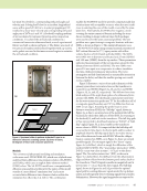
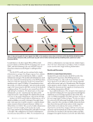
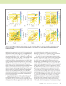
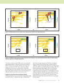
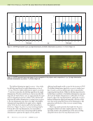
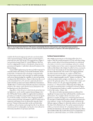
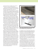
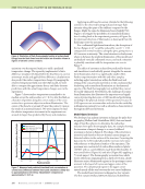
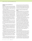
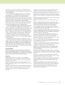
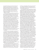
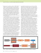
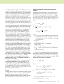
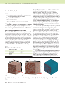
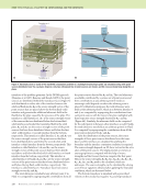
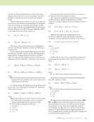
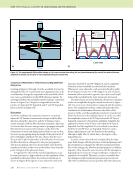
96 M A T E R I A L S E V A L U A T I O N • J A N U A R Y 2 0 2 0 In this paper we discuss how we tackled each of those problems in the context of a model-based inversion process for pulse (flash) thermography NDE (Holland and Schiefel- bein 2019) and our development of a new open-source library (“spatialnde2”) designed to help others make use of 3D CAD geometry in NDE modeling and analysis. We discuss the benefits and challenges of performing data analysis in the 3D CAD domain. Pulse Thermography Pulse (flash) thermography uses a pulse of energy to a surface, perhaps from a laser or xenon flash tube, to identify disconti- nuities in materials by observing the cooling of the surface with a thermal camera (Maldague 2001). Basic apparatus for pulse thermography is shown in Figure 1. The flash hood contains a pair of xenon flash lamps that project a pulse of energy to the surface of the specimen. The thermal camera then captures an image sequence as the surface cools. Discontinuity zones parallel to the surface, such as a delamination in a composite material, will cool more slowly, giving contrast. The usual analysis of pulse thermography, thermographic signal reconstruction (Shepard et al. 2007), involves fitting curves to the temperature-time profile at each pixel, and looking at contrast in the time derivatives. While thermographic signal recon- struction is very effective and very sensitive, the derivative analysis is based on one-dimensional through-thickness heat flow. Where heat flows are more complicated, such as near small delamina- tions, delamination boundaries, edges of the specimen, and sharp bends, the resulting derivative images are difficult to interpret. They represent (at best) the rather abstract concept of change in dimensionality of conduction. Thermographic signal reconstruction analysis is based on one-dimensional conduction in large part because the one- dimensional analysis allows an independent analysis of each pixel in the image sequence. Any model explicitly based on higher-dimensional heat flows would need to know lateral pixel spacing, and determining pixel spacing in an image with an arbitrary camera position of an object with nontrivial geometry requires registering the detailed geometry (CAD model). If the object is flat or near flat and orthogonal to the camera, then the pixel spacing can be approximated as uniform and evaluated from a known distance marked on the surface as an alternative to the CAD model. A perspective correction can help compensate if the specimen is not orthog- onal to the camera. Once the specimen geometry and orientation are known, each pixel in the NDE image can be traced back as a ray that passes through the thermal camera lens and intersects with the CAD model. The thermal images can thereby be mapped into the CAD domain where geometric features such as pixel spacing and curvature are known. Raytracing and Pose Estimation The process of tracing rays from between an image and CAD model is represented in Figure 2. The camera is modeled as an idealized pinhole camera (Bradski 2000) with its focal point at the origin. The Z axis represents the axis of the camera. The imaging plane is located at z = f where the focal length f, measured in pixels, determines the scaling of the image. Each pixel is represented by a ray connecting the origin, an image point (a, b) at the imaging plane, and the physical point imaged P = (X, Y, Z). The physical point P maps to image coordinates (a, b) relative to the image center according to (1) By convention, the focal length f is scaled such that a and b will be measured in pixel image coordinates for a particular camera and lens. Real cameras and lenses are not quite so ideal as presented here. The open source package, OpenCV (Bradski 2000), provides tools for calibrating out lens distor- tions and measuring separate focal lengths fx and fy for the X and Y axes. Given the CAD model represented as a surface mesh with known position and orientation (pose) relative to the camera, the inverse of Equation 1 can map a point in image coordinates onto the closest facet of the CAD model that intersects the pixel’s ray. Even when the specimen position and orientation are not yet known, Equation 1 can be used to help solve for the unknown rotation and translation between CAD coordinates and camera coordinates. In our first implementation, we determine the transformation by defining identifiable land- marks on the specimen with vaguely pronounceable names, and having the operator identify the locations of these land- marks in the thermal images. In general, knowing both CAD and image coordinates of at least four noncoplanar landmarks is sufficient to solve for the relative position and orientation of the camera. The open source OpenCV library (Bradski 2000) provides implementa- tions solvePnP and solvePnPRansac of the standard computer vision algorithms that solve for object pose. Figure 3 shows a CAD model with landmarks, a thermal image with landmarks %a" $b! # = f 0 0 f % $ # "% ! X/Z Y/Z $ # " ! ME TECHNICAL PAPER w nde modeling in 3d cad Flash hood Flash lamp Specimen Thermal camera Figure 1. Apparatus from flash thermography showing the thermal camera, flash hood, flash lamp, and specimen.

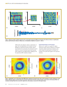
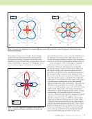
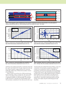
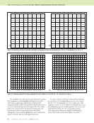
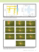
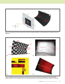
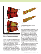
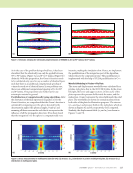
J A N U A R Y 2 0 2 0 • M A T E R I A L S E V A L U A T I O N 97 Y X b a Z Camera axis Object z = –f P 1 = (a 1 ,b 1 ) P 1 = (x 1 ,y 1 ,z 1 ) P 2 = (x 2 ,y 2 ,z 2 ) (0,0) P 2 = (a 2 ,b 2 ) Figure 2. Tracing rays from the camera focal point (at the origin) to landmarks identified on the thermal image and to landmarks locations on CAD model. GOWJOT BESRUZ GOWJOT projected BESRUZ projected SUNJIC SUNJIC projected YOVWAW SIKNAT SIKNAT projected JERNUH CERNON CERNON projected YOVWAW projected LIQYES projected LIQYES Figure 3. Registration preformed using OpenCV’s solvePnPRansac function: (a) CAD model showing landmarks (b) thermal image with landmarks identified (c) thermal image projected onto surface parameterization and (d) surface parameterization mapped onto CAD model. (c) (d) (a) (b)
ASNT grants non-exclusive, non-transferable license of this material to  .
All rights reserved. © ASNT 2026. To report unauthorized use, contact: customersupport@asnt.org