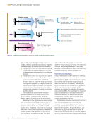
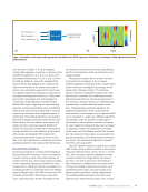
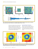
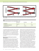
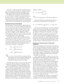
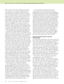
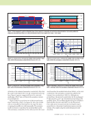
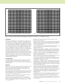
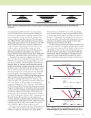
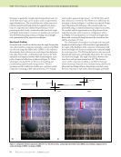
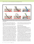
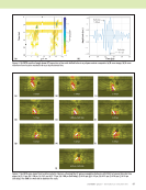
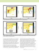
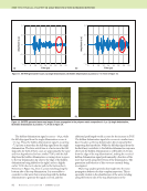
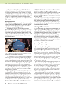
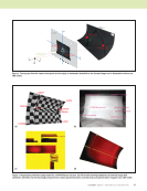
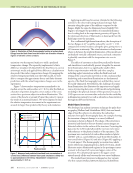
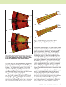
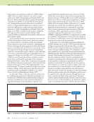
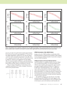
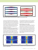
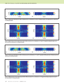
are essentially average values that will be taken to be equal for example, it is impossible to distinguish the direction of the contact between the fibers. Hence, we define only a single transverse conductivity, sy = sz = sT = 100 S/m as listed in Table 1, where sL = sx = 2 × 10⁴. Furthermore, the most general expression for a biaxial conductivity tensor includes the off-diagonal terms, sxy = syx, but these will be taken to be zero since we have no information as to what they might be (see Table 1). Eddy Current Coil and Technique for Carbon Fiber Characterization The capabilities of eddy current techniques for characteriza- tion of carbon fiber composites have been investigated through detailed electromagnetic modeling. A trial model simulating a transmit-receive (T/R) coil pair, operating at 10 MHz, over a four-layer composite has been constructed. Along with a baseline 0/90/90/0 layup, perturbed layups at 0/0/90/90 and 0/90/90/90 are considered. In accordance with Table 1, the anisotropic carbon fiber composite was modeled using a diagonal conductivity tensor with a conduc- tivity of 2 × 10⁴ S/m along the ply direction and 100 S/m in the orthogonal directions. For an isotropic host with a conductivity of 2 × 10⁴ S/m, the skin depth is 1.12 mm at the frequency of interest. The specific coils modeled were 4 mm inside diameter × 6 mm outside diameter × 2 mm tall, with a center-to-center spacing between the coils of 9 mm. The coil liftoff was modeled at 0.07 mm. Each carbon fiber ply was modeled at a thickness of 0.2 mm. Software based on the volume-integral approach (Sabbagh et al. 2013) was used to produce and solve the model. The coil angle, defined as the angle of the transmit to receive coil displacement vector, was parameterized in π/16 radian increments. Figure 2 shows polar plots of the resistance and reactance as the coil is rotated 360° over composite layups of 0/90/90/0 and 0/0/90/90. In both cases the change in impedance due to the presence of the conducting fibers is seen to produce local maxima in the reactance and minima in the resistance when the coil angle corresponds to any of the ply angles in the part. An alternate way to view the results shown in Figure 2 is to plot the magnitude of the impedance change referenced to a given probe orientation. The reference orientation would typically be away from expected ply angles so as to maximize the response as the coil angle aligns with any of the plies in the part. For a composite with ply angles at 0° and 90°, this response can be simulated by subtracting the calculated response at 45° from the array of measured values. The results are shown in Figure 3, given as a polar plot of the magnitude of 74 M A T E R I A L S E V A L U A T I O N • J A N U A R Y 2 0 2 0 ME TECHNICAL PAPER w eddy current characterization for cfrp composites Applied field Current path Fibers Resin matrix Eddy current path Capacitance Resistance Figure 1. Illustration of CFRP microstructure: (a) how fiber-to-fiber contact allows transverse conduction (b) possible AC equivalent circuit for eddy current flow. (a) (b) TABLE 1 Summary of electrical properties of some composites (Allan et al. 1975) Graphite-Epoxy Boron-Epoxy Kevlar Permeability (μR) 1 1 1 Permittivity (%R) Indeterminate 5.6 3.6 DC conductivity (S/m): longitudinal (sL) 2 × 10⁴ 30 6 × 10⁻⁹ DC conductivity (S/m): transverse (sT) 100 2 × 10⁻⁸ 6 × 10⁻⁹ Anisotropy ratio (sL/sT) 200 1.5 × 10⁹ 1

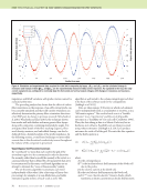
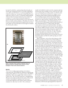
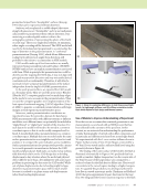
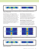
J A N U A R Y 2 0 2 0 • M A T E R I A L S E V A L U A T I O N 75 the impedance change versus coil angle. The plot displays results for the three-ply layups introduced previously. For the asymmetrical layups, an asymmetry in the lobes of the impedance is seen, with larger lobes corresponding to the near surface (0/0/90/90) or majority (0/90/90/90) ply orienta- tions. In contrast, Figures 2 and 3 show the 0/90/90/0 symmetrical layup to have a more symmetrical distribution of the impedance as a function of the angle. These data show that the eddy current technique is sensitive to not only ply direc- tion, but also specific ply layup through the thickness of the part. A direct comparison of the electromagnetic modeling results discussed above and experimental data has been performed. A T/R probe with dimensions matching the model problem was constructed. The probe was fabricated such that it could be easily rotated around the axis of the transmitter coil, with the receiver coil orbiting in the plane of the transmitter coil at a center-to-center distance of 9 mm between the coils. The probe was driven at 10 MHz. Orienta- tion of the impedance plane was performed by rotating the liftoff response from an aluminum 6061 sample to the positive vertical direction, resulting in the reactive axis nominally aligned vertically on the eddy current display. The probe was then balanced in air and placed on a four-ply carbon fiber compression molded prepreg sample with a 0/90/90/0 layup. Further details of the sample can be found in the literature (Wincheski et al. 2016 Wincheski and Zhao 2018). Voltages corresponding to the horizontal (resistive) and vertical (reactive) components of the impedance change were acquired as the probe was rotated 360° under stepper motor control. The data are displayed in Figure 4. While the simulation plots (dashed) show reflection symmetry about 0° and 90°, careful examination of the experimental data reveals a slight change in the peak height and positions through the 360° rotation. These variations are likely attributable to changes in the carbon fiber orientation and densities caused by the compression molding process (Menana and Féliachi 2010), although experimental errors associated with background effects such as stray 0 30 60 90 120 150 180 210 240 270 300 330 0 1 2 |R| |X| 0 30 60 90 120 150 180 210 240 270 300 330 0 0.5 1 1.5 2 |R| |X| Figure 2. Polar plot of the magnitude of the resistance (|R|) and reactance (|X|) calculated for carbon fiber layups: (a) 0/90/90/0 ply layup (b) 0/0/90/90 ply layup. (a) (b) 0 30 60 90 120 150 180 210 240 270 300 330 0 1 2 0/90/90/0 0/0/90/90 0/90/90/90 Figure 3. Polar plot of magnitude of impedance versus angle for T/R coil over composites with layups of 0/90/90/0, 0/0/90/90, and 0/90/90/90.
ASNT grants non-exclusive, non-transferable license of this material to  .
All rights reserved. © ASNT 2026. To report unauthorized use, contact: customersupport@asnt.org