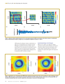
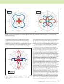
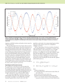
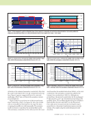
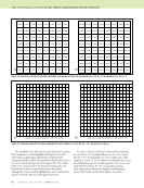
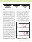
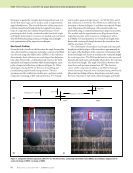
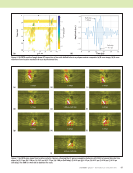
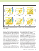
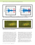
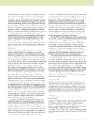
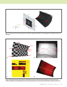
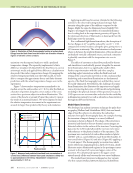
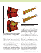
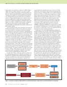
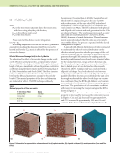
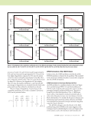
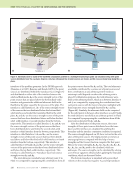
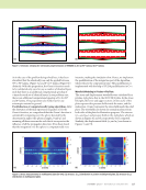
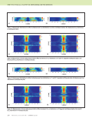
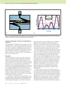
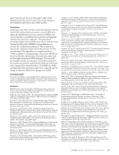
80 M A T E R I A L S E V A L U A T I O N • J A N U A R Y 2 0 2 0 The capabilities for eddy current crack detection in carbon fiber composites are also highlighted in Figure 10. For the cells of the cracked region, the inversion results for the component of the conductivity parallel to the fiber direction is seen to be identically reproduced in Figure 10b. The conduc- tivity of the cracked cells in the direction orthogonal to the fiber direction shows some deviation from the model, although the crack is clearly highlighted as a low conductivity region in both the fiber and orthogonal directions. In order to check consistency in the model calculations, we reran the 8 × 8 × 4 grid problem on a 16 × 16 × 8 grid. The 16 × 16 × 8-cell grid has 16 × 15 × 6 unknown coeffi- cients for Jx and 16 × 15 × 6 unknown coefficients for Jy, and thus 2880 unknowns for the data equation. The receive scan used with this grid has 81 × 81 scan positions, giving 6561 equations, and thus also a highly overdetermined system. The results are shown in Figures 11 and 12. ME TECHNICAL PAPER w eddy current characterization for cfrp composites Figure 10. Inversion results for 90 ply with embedded crack shown in Figure 5b: (a) anomalous σxx for m = 2 (b) anomalous σyy for m = 2. (a) (b) Values not shown lie between –4E-06 and 4E-06 Values not shown lie between 19 865 and 19 959 Figure 11. Inversion results for the layer containing the crack, z plane m = 4, for the 16 × 16 × 8 grid: (a) σxx (b) σyy. (a) (b)

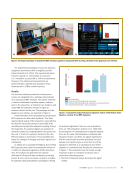
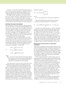
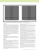
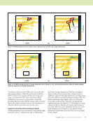
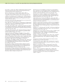
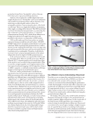
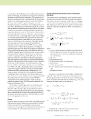
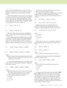
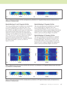
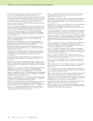
Conclusion The purpose of this paper is to demonstrate an approach to the detailed characterization of CFRPs using highly sophisti- cated, robust inversion algorithms. The principal conclusion to be drawn is that the set-theoretic algorithm for electromag- netic voxel-based inversions can be applied with great effec- tiveness to highly anisotropic materials such as CFRPs. The information that can be acquired is much more detailed than any other technique currently in use. The next step is to develop systems based on our ideas that will be used to gain experimental data for further processing. At this time, we aim to apply such systems to those parts of the CFRP industry that are developing prepregs and in research labs fabricating complex CFRP composites. ACKNOWLEDGMENT This work was supported in part by the NASA Langley Research Center under SBIR grants to Victor Technologies LLC. The software used throughout this project is VIC-3D® v. 4.3.9 from Victor Technologies LLC, Bloomington, IN. REFERENCES Allen, J.L., A.T. Adams, W.J. Gajda, R.E. Heintz, W.F. Walker, O. Graham, and J.E. Erickson, 1978, “Electromagnetic Properties and Effects of Advanced Composite Materials: Measurement and Modeling,” Phase Report, RADC-TR-78-156, ADA 058041. Arao, Y., J. Koyanagi, S. Utsunomiya, and H. Kawada, 2011, “Effect of Ply Angle Misalignment on Out-of-Plane Deformation of Symmetrical Cross- Ply CFRP Laminates: Accuracy of the Ply Angle Alignment,” Composite Structures, Vol. 93, No. 4, pp. 1225–1230. Combettes, P.L., 1993, “The Foundations of Set Theoretic Estimation,” Proceedings of the IEEE, Vol. 81, No. 2, pp. 182–208. Fast, T., A.E. Scott, H.A. Bale, and B.N. Cox, 2015, “Topological and Euclidean Metrics Reveal Spatially Nonuniform Structure in the Entang lement of Stochastic Fiber Bundles,” Journal of Materials Science, Vol. 50, No. 6, pp. 2370–2398. Libby, H.L., 1971, Introduction to Electromagnetic Nondestructive Test Methods, Wiley, New York, NY. Menana, H., and M. Féliachi, 2010 “Modeling the Response of a Rotating Eddy Current Sensor for the Characterization of Carbon Fiber Reinforced Composites,” European Physical Journal: Applied Physics, Vol. 52, No. 2, doi: 10.1051/epjap/2010079. ASNT, 1986, Nondestructive Testing Handbook, Second Edition, Vol 4: Elec- tromagnetic Testing, American Society for Nondestructive Testing, Columbus, OH, pp. 22-51. Sabbagh, H.A., R.K. Murphy, E.H. Sabbagh, J.C. Aldrin, and J.S. Knopp, 2013, Computational Electromagnetics and Model-Based Inversion: A Modern Paradigm for Eddy-Current Nondestructive Evaluation, Springer-Verlag, New York, NY. Schrader, A., and D. Kenick, 2015, “Understanding the Influence of Fiber Orientation On Structural Analysis of Fiber-Filled Parts,” Composites World, accessed 1 June 2015, at: https://www.compositesworld.com/articles/understanding-the-influence- of-fiber-orientation-on-structural-analysis-of-fiber-filled-parts. Treece, J.C., H.A. Sabbagh, and B.F. Shamee, 1990, “Sabbagh Associates Technical Report SA/TR- 1/90, Final Report: Eddy-Current Detection of Prepreg FAWT,” Sabbagh Associates Inc. Washabaugh, A., C. Martin, R. Lyons, D. Grundy, N. Goldfine, R. Russell, R. Wincheski, and V. Zilberstein, 2013, “NDT and SHM of Carbon Fiber Composites Using Linear Drive Mwm-Arrays,” 24th Advanced Aerospace Materials and Processes (AeroMat) Conference and Exposition, American Society of Metals, Bellevue, WA. Wincheski, B., and J. Simpson, 2006, “Application of Eddy Current Tech- niques for Orbiter Reinforced Carbon-Carbon Structural Health Moni- toring,” AIP Conference Proceedings, Vol. 820, No. 1, pp. 1082–1089. Wincheski, R., S. Zhao, and L. Berger, 2016, “Fiber Orientation Assessment on Laminated Carbon Fiber Composites Using Eddy Current Probe,” The American Society for Composites: 31st Technical Conference, Williamsburg, VA. Wincheski, R.A., and S. Zhao, 2018, “Development of Eddy Current Probe for Fiber Orientation Assessment in Carbon Fiber Composites,” AIP Conference Proceedings, Vol. 1949, No. 1, doi: 10.1063/1.5031591. Wisnom, M.R., 1990, “The Effect of Fibre Misalignment on the Compres- sive Strength of Unidirectional Carbon Fibre/Epoxy,” Composites, Vol. 21, No. 5, pp. 403–407. Values not shown lie between –3.5E-06 and 4.5E-06 Values not shown lie between 19 871 and 19 928 Figure 12. Inversion results for the layer containing the crack, z plane m = 5, for the 16 × 16 × 8 grid: (a) σxx (b) σyy. (a) (b) J A N U A R Y 2 0 2 0 • M A T E R I A L S E V A L U A T I O N 81
ASNT grants non-exclusive, non-transferable license of this material to  .
All rights reserved. © ASNT 2026. To report unauthorized use, contact: customersupport@asnt.org