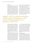
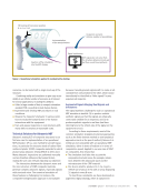
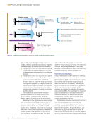
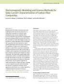
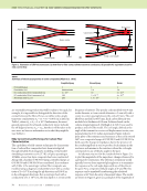
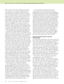
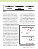
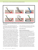
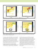
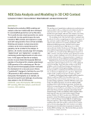
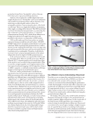
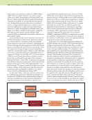
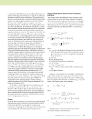
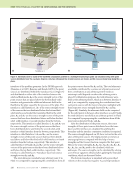
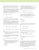
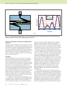
106 M A T E R I A L S E V A L U A T I O N • J A N U A R Y 2 0 2 0 improvements were made by Lenglet et al. (2003), Berger (2005), Moreno (2009), Medeiros et al. (2012), Swami- nathan et al. (2006), Swaminathan and Ghosh (2006), and Qin et al. (2014) to find the effective material properties of composites from RVEs. It was found that for most general cases, finding all the material coefficients in a constitutive matrix to compute full field displacement and stress Green’s function is difficult, but an approach proposed by Swami- nathan et al. (2006), Swaminathan and Ghosh (2006), and Berger et al. (2005) is suitable for this purpose. Using this RVE approach, both pristine and discontinuity filled composite RVEs are simulated to obtain all the coefficients in a full constitutive matrix. As discussed previously, Green’s function is necessary for DPSM, and calculations of the Green’s function in compos- ites is reviewed herein. Calculations of the elastodynamic Green’s function in anisotropic material is a challenging task. Various techniques have been proposed to derive the Green’s function and understand wave behavior in anisotropic media. The Cagniard de Hoop technique was proposed by Kraut (1963) for a transversely isotropic half space and by Burridge (1971) for an anisotropic half space. A simplified version of Cagniard de Hoop is used by Willis (1972, 1991) and Payton (1983) for several anisotropic half space problems. Green’s function for an unbounded, anisotropic elastic medium is developed by Yeatts (Yeatts 1984). Computation of a general- ized 3D Green’s function in anisotropic solids is presented by Wang and Achenbach (1992, 1993) applying Radon’s trans- form technique. The fourier transform technique is presented by Every and Kim (1996). The Green’s function in layered anisotropic media is published by Glushkov et al. (2011), Krowne (1984), and Michalski and Mosig (1997). As depicted in Figure 1, this paper presents a framework by combining the material state degradation technique and the ultrasonic CNDE models to understand the changes in ultrasonic wavefields due to microscale discontinuities in degraded anisotropic media. Speaking in a general sense, several multiscale material models exist (Tavaf et al. 2018a, 2018b) that can provide the represented material properties. However, for most CNDE models we need a full constitutive matrix (Cijkl). Hence, we first present results from a compre- hensive finite element multiscale model (Tavaf et al. 2018a, 2018b, 2019) to compute all the coefficients in a Cijkl matrix affected by microvoids. Then we utilize the pristine and degraded material properties in computing the anisotropic Green’s function presented in previous research (Shrestha and Banjeree 2018). Applying the symmetry informed sequential mapping of the anisotropic Green’s function (SISMAG) implemented DPSM, we computed the wavefield in a multilayer composite plate to demonstrate the change in the ultrasonic wavefield due to macroscale degraded material properties from microscale discontinuities. In this paper, the virtual NDE experiments utilizing the DPSM technique with a notable CNDE framework depicted in Figure 1 are presented for the first time. For a case study, DPSM is used to simulate the ultrasonic wavefield in a homoge- neous anisotropic multilayered plate. The simulation in 1-ply plate and half space has previously been presented without any CNDE framework (Shrestha and Banerjee 2018 Banerjee and Shrestha 2018 Shrestha and Banerjee 2017 Shrestha 2017 Shrestha and Banerjee 2016). A pristine and degraded state multilayered anisotropic plate submerged in water is considered for the simulation. In this paper, a generalized case with two transducers is presented. Two transducers, one above and one below the plate, are used for the acoustic excitation. When only one transducer on one side of the plate is excited and the same transducer is used for sensing, then the setup will represent a pulse-echo mode. However, if a transducer on one side is excited but the transducer on the other side of the plate is used to sense the signal, then the setup will represent a through transmission mode. Using the simulation setup in this paper, both modes could be explored simultaneously. However, when both trans- ducers are active (or the channels are on), then both could be used as a transmitter and receiver, and then the mode will be ME TECHNICAL PAPER w computational nde for composites Multiscale model RVE with and without discontinuities CNDE library Variation in signals due to degraded material properties Quantification of damaged and degraded material properties Revised model with damage geometry and material properties Progressive failure model NDE experiment on real specimen NDE data Virtual NDE models (CNDE) Pristine material properties Material properties with microscale discontinuities Figure 1. A schematic showing the CNDE framework for understanding ultrasonic signals with microscale discontinuities in a composite.

J A N U A R Y 2 0 2 0 • M A T E R I A L S E V A L U A T I O N 107 a superposition of both the pulse-echo and through transmission modes. In this study, two transducers are kept on, for enhancing the ultrasonic field for better visualization. The transducers are excited in a normal direction to represent both the superposition of pulse-echo and through transmission modes. Nevertheless, the framework is flexible to operate only pulse-echo, only through transmission, or both pulse-echo and through transmis- sion modes. Additionally, the framework is flexible to accommo- date any number of transducers and at any location, if necessary. It can also accommodate an inclined transducer excitation for angle beam ultrasonic scenarios. The objective of this article is to understand the effect of microscale damages or discontinuities on wave behavior in an anisotropic plate (composites) such that we can better understand the NDE signals that are affected by microscale discontinuities. Such studies are rare as proposed under the CNDE framework in this paper. Although a detailed understanding of the ultrasonic signals and quantifying the degraded material properties from the NDE data seems to be a long-term dream, we believe this study serves as a foundation toward the bigger goal of the digital NDE pipeline and digital twin. This paper does not promise to give a clear definition on how to classify the degraded signals, but rather provides an opportunity to study this problem with greater effort. Moreover, with current available computing technology at affordable prices, it is chal- lenging to validate the computation results in the experiments thus, only frequency domain signals are presented. Nevertheless, validation of the presented work is in progress. A basic calculation shows that a CNDE simulation of an NDE experiment with a pulse of ~1 MHz central frequency (frequency content 500 KHz to 10 MHz) with 100 μs signal length requires at least 107 data points when sampled at 100 Ms/s. This means that the DPSM simulation should be performed with a minimum of 5 × 10⁶ frequency points. Even with the CUDA-enabled GPU, parallel computing would be very expensive to perform at this point in time. However, to achieve confidence on the computed wavefield, the calculated Green’s function (which is part of DPSM) is verified with various existing techniques, and the results are published elsewhere (Yeatts 1984 Wang and Achenbach 1992 Wang and Achenbach 1993). In this paper, terminologies, previous calculations, and techniques are implemented under one framework. The objective of this study is to demonstrate the framework in a novel way, integrating the blocks or the technical challenges that are independently developed through parallel efforts by the authors and other researchers. They are briefly reviewed herein with appropriate references. Theory From the above discussion, it is clear that one would need the elastodynamic Green’s function to proceed with the CNDE problem using DPSM. Accordingly, the mathematical equation for computing the elastodynamic Green’s function is presented when the material property matrix is known. Solution of Elastodynamic Green’s Function in Anisotropic Bulk Media The solution of the elastodynamic Green’s function can be obtained from the fourier and radon transform techniques. The authors have previously proved that the two techniques can be used interchangeably (Shrestha and Banerjee 2018). The displacement Green’s function equations that have been developed (Shrestha and Banerjee 2018) are presented as follows: (1) where gmp (cn, w) is the frequency domain Green’s function in the m-th direction at a point (y) away from the source point (y0), due to a unit force amplitude acting along the p-th direction, x = |y – y0|, x is the position vector, w is the monochromatic wave frequency, r is the density, gz is the z-th eigen value, (Pmp)(z) is the projection matrix of the z-th eigen mode, and si is the phase slowness. Equation 1 is an integral over unit sphere with spherical angles, q and j. After the computation of the displacement Green’s function, the stress Green’s function is further calcu- lated. The displacement function is rewritten as gmp = um. p The strains at the target points can be written as (2) where (3) Using Equation 2, the stress Green’s tensor in the anisotropic medium can be written as g mp x n ,3 ( ) = i3 8221 0=0 /=0 0= 2 2 /=22 .. z=1 3 - 1 , z + * ) ( ’ & 3 mp +P * ( ’ [z] exp i s i x i ( )(z)(sin0d0d/ + * ’ % $ # # " ! + 1 2 22 ( )2 1 x 0 22 . 1 , z % $ # # "2 ! Pmp ( )(z) d/ u up,mj 1 2 m j p , ( ) °pmj = + u m, j p x n , 3) ( = 2 3) ( 2 2 21) ( 2 0 /=0 .=0 /=1 .=21 -- z=1 3 , z ) 4 + *Pmp ) ( +z) k j exp i s i x i ( )(z) + * ) ( sin /d/d. % $ #+s " ! 2 x j 2 21) ( 2 0 x 3 0 21 - s z ( ) 2 P mp ( )(z) d.
ASNT grants non-exclusive, non-transferable license of this material to  .
All rights reserved. © ASNT 2026. To report unauthorized use, contact: customersupport@asnt.org